Additional installation of oil pressure relief valve in main oil duct
|
|
||||||||||||||||||||||||||||||||||||||||||
|
18—020 Additional installation of oil pressure relief valve in main oil duct
|
||||||||||||||||||||||||||||||||||||||||||
|
|
||||||||||||||||||||||||||||||||||||||||||
|
||||||||||||||||||||||||||||||||||||||||||
|
|
||||||||||||||||||||||||||||||||||||||||||
|
) only for models with fuel evaporation system, which have connection at plug.
|
||||||||||||||||||||||||||||||||||||||||||
|
|
||||||||||||||||||||||||||||||||||||||||||
|
Note
|
||||||||||||||||||||||||||||||||||||||||||
|
|
||||||||||||||||||||||||||||||||||||||||||
|
In the event of repairs or when installing an oil pump drive, part no. 110 050 02 06, install a 5 bar pressure relief valve, part no. 114 118 02 15 into main oil duct front in addition to pressure relief valve in oil pump. For this purpose, use a new closing plug.
On vehicles with fuel evaporation control system without charcoal canister, install line of evaporation control system from cylinder crankcase to cylinder head.
|
||||||||||||||||||||||||||||||||||||||||||
|
|
||||||||||||||||||||||||||||||||||||||||||
|
Standard installation 5 bar pressure relief valve in main oil duct
Engine starting engine end no.
110.921 – 10- 008705
– 12- 035819
110.922- 10- 015494
– 12- 022259
110.923 – 10 – starting begin of series
– 12 — starting begin of series
110.931 – 10- 001058
– 12- 000126
|
||||||||||||||||||||||||||||||||||||||||||
|
|
||||||||||||||||||||||||||||||||||||||||||
|
18.2-020/1 F3
|
||||||||||||||||||||||||||||||||||||||||||
|
|
||||||||||||||||||||||||||||||||||||||||||
|
|
||||||||||||||||||||||||||||||||||||||||||||||||||||||||||||||||||||||||||||||||||||||||||||||||||||||||||||||||||||||||||||||||||
|
||||||||||||||||||||||||||||||||||||||||||||||||||||||||||||||||||||||||||||||||||||||||||||||||||||||||||||||||||||||||||||||||||
|
|
||||||||||||||||||||||||||||||||||||||||||||||||||||||||||||||||||||||||||||||||||||||||||||||||||||||||||||||||||||||||||||||||||
|
All exchange engines starting unit no. 464130 are provided with 5 bar pressure relief valve in main oil duct.
|
||||||||||||||||||||||||||||||||||||||||||||||||||||||||||||||||||||||||||||||||||||||||||||||||||||||||||||||||||||||||||||||||||
|
|
||||||||||||||||||||||||||||||||||||||||||||||||||||||||||||||||||||||||||||||||||||||||||||||||||||||||||||||||||||||||||||||||||
|
Removal
|
 |
|||||||||||||||||||||||||||||||||||||||||||||||||||||||||||||||||||||||||||||||||||||||||||||||||||||||||||||||||||||||||||||||||
|
1 Remove radiator (20-420).
|
||||||||||||||||||||||||||||||||||||||||||||||||||||||||||||||||||||||||||||||||||||||||||||||||||||||||||||||||||||||||||||||||||
|
2 Remove fan clutch.
|
||||||||||||||||||||||||||||||||||||||||||||||||||||||||||||||||||||||||||||||||||||||||||||||||||||||||||||||||||||||||||||||||||
|
3 Remove pulley and vibration damper (03-340).
|
||||||||||||||||||||||||||||||||||||||||||||||||||||||||||||||||||||||||||||||||||||||||||||||||||||||||||||||||||||||||||||||||||
|
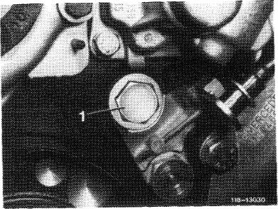
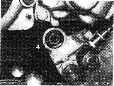
4 Remove plug (1).
|
||||||||||||||||||||||||||||||||||||||||||||||||||||||||||||||||||||||||||||||||||||||||||||||||||||||||||||||||||||||||||||||||||
|
|
||||||||||||||||||||||||||||||||||||||||||||||||||||||||||||||||||||||||||||||||||||||||||||||||||||||||||||||||||||||||||||||||||
|
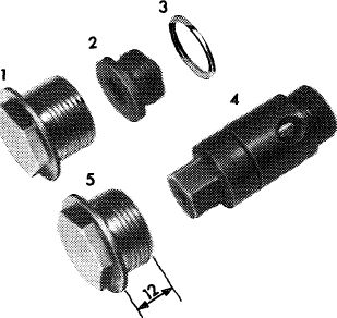
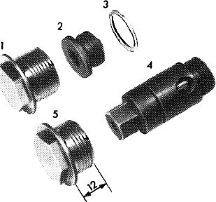
5 Unscrew plug (2) for oil bore with a lubricated
8 mm internal socket wrench and pull out carefully.
6 For protection insert a long piece of welding wire in oil bore and remove the press fit aluminium seal (3) from countersink of oil bore with a screwdriver.
|
 |
118 -K) 386
|
||||||||||||||||||||||||||||||||||||||||||||||||||||||||||||||||||||||||||||||||||||||||||||||||||||||||||||||||||||||||||||||||
|
|
||||||||||||||||||||||||||||||||||||||||||||||||||||||||||||||||||||||||||||||||||||||||||||||||||||||||||||||||||||||||||||||||||
|
18.2-020/2 F3
|
||||||||||||||||||||||||||||||||||||||||||||||||||||||||||||||||||||||||||||||||||||||||||||||||||||||||||||||||||||||||||||||||||
|
|
||||||||||||||||||||||||||||||||||||||||||||||||||||||||||||||||||||||||||||||||||||||||||||||||||||||||||||||||||||||||||||||||||
|
|
|||||
|
Attention!
Do not use old closing plug (1), 16 mm long, together with pressure relief valve (4).
When installing a 5 bar pressure relief valve, use screw connection (5), part no. 110 184 0056 (or part no. 110 184 0156 with tank breather on vehicles for (aus) , (T) ,(usa)), since otherwise the pressure relief valve will not operate.
|
 |
118-10386
|
|||
|
|
|||||
|
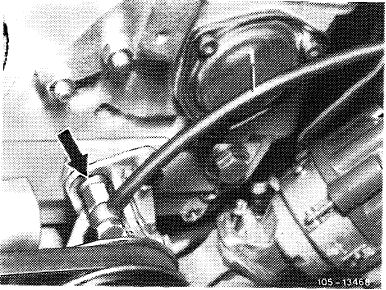
For subsequent installation of a 5 bar pressure relief valve into the following vehicle models, connect line of fuel evaporation control system to cylinder head (arrow):
|
 |
||||
|
Model years
|
1977.
|
||||
|
(aus) starting 10.1974 up to start of model year
|
|||||
|
<T) starting 1.1973 up to start of model year 1976. (@) starting model year 1972 to 1974.
For this purpose, use conversion set, part no. 114 010 26 99. Also refer to repair instructions engine 110, combustion III, programmed repairs, group 47.
|
|||||
|
|
|||||
 |
|||||
|
|
|||||
|
Installation
|
|||||
|
|
|||||
|
7 Install pressure relief valve (4) and torque to 40 Nm.
8 Coat threads of new plug (5) with a sealing compound, install and torque to 50 Nm.
9 Install vibration damper and pulley.
|
|||||
|
|
|||||
|
18.2-020/3 F3
|
|||||
|
|
|||||
|
|
||
|
10 Install fan clutch.
11 Install and tighten belt.
12 Install radiator housing and radiator.
13 Add coolant.
14 Run engine, check oil pressure and for leaks.
|
||
|
|
||
|
18.2-020/4 F2
|
||
|
|
||