Checking and renewing valve guides
|
|
||||||||||||||||||||||||||||||||||||||||||||||||||||||||||||||||||||||||
|
05—285 Checking and renewing valve guides
|
||||||||||||||||||||||||||||||||||||||||||||||||||||||||||||||||||||||||
|
|
||||||||||||||||||||||||||||||||||||||||||||||||||||||||||||||||||||||||
|
Data
|
||||||||||||||||||||||||||||||||||||||||||||||||||||||||||||||||||||||||
|
|
||||||||||||||||||||||||||||||||||||||||||||||||||||||||||||||||||||||||
|
Valve guide
|
Part No.
|
Version
|
Color code
|
OD
|
Bore in
cylinder
head
|
Overlap
|
Valve guide ID
|
Length
|
Shape of valve guide
|
|||||||||||||||||||||||||||||||||||||||||||||||||||||||||||||||
|
|
||||||||||||||||||||||||||||||||||||||||||||||||||||||||||||||||||||||||
|
Intake
|
621 053 15 29 616 053 00 291)
|
Normal dimension
|
14.04 14.03
|
14.00 14.02
|
 |
|||||||||||||||||||||||||||||||||||||||||||||||||||||||||||||||||||
|
l 601)
|
||||||||||||||||||||||||||||||||||||||||||||||||||||||||||||||||||||||||
|
621 053 16 29 616 053 01 291)
|
Repair stage
|
red
|
14.24 14.23
|
14.20 14.22
|
10.000 10.015
|
|||||||||||||||||||||||||||||||||||||||||||||||||||||||||||||||||||
|
621 053 36 30 616 053 00 301)
|
Normal dimension
|
+ 0.01 up to + 0.04
|
||||||||||||||||||||||||||||||||||||||||||||||||||||||||||||||||||||||
|
14.04 14.03
|
14.00 14.02
|
49.5 48.51)
|
||||||||||||||||||||||||||||||||||||||||||||||||||||||||||||||||||||||
|
Exhaust
|
14.24 14.23
|
|||||||||||||||||||||||||||||||||||||||||||||||||||||||||||||||||||||||
|
621 053 37 30 616 053 01 301)
|
Repair stage
|
red
|
14.20 14.22
|
3000-3500 N
|
||||||||||||||||||||||||||||||||||||||||||||||||||||||||||||||||||||
|
Tight fit test pressure
|
||||||||||||||||||||||||||||||||||||||||||||||||||||||||||||||||||||||||
|
Wear limit of valve guide ID (measuring point 5 mm above valve guide bottom edge)
|
0.20
|
|||||||||||||||||||||||||||||||||||||||||||||||||||||||||||||||||||||||
|
|
||||||||||||||||||||||||||||||||||||||||||||||||||||||||||||||||||||||||
|
M These valve guides are 1 mm shorter (refer to note).
|
||||||||||||||||||||||||||||||||||||||||||||||||||||||||||||||||||||||||
|
|
||||||||||||||||||||||||||||||||||||||||||||||||||||||||||||||||||||||||
|
Special tools1)
|
||||||||||||||||||||||||||||||||||||||||||||||||||||||||||||||||||||||||
|
|
||||||||||||||||||||||||||||||||||||||||||||||||||||||||||||||||||||||||
|
||||||||||||||||||||||||||||||||||||||||||||||||||||||||||||||||||||||||
|
|
||||||||||||||||||||||||||||||||||||||||||||||||||||||||||||||||||||||||
|
’) Same for intake and exhaust.
|
||||||||||||||||||||||||||||||||||||||||||||||||||||||||||||||||||||||||
|
|
||||||||||||||||||||||||||||||||||||||||||||||||||||||||||||||||||||||||
|
05.8-285/1 F 2
|
||||||||||||||||||||||||||||||||||||||||||||||||||||||||||||||||||||||||
|
|
||||||||||||||||||||||||||||||||||||||||||||||||||||||||||||||||||||||||
|
|
||||
|
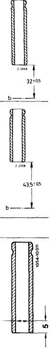
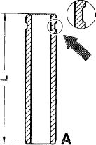
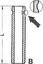
Note
The valve guides 61 mm or 49.5 mm long have been replaced by valve guides 60 mm or 48.5 mm long.
In addition to their length, the valve guides are also different with regard to the shape of their grooves (arrows).
|
 |
 |
||
|
A Valve guide = 61 mm or 49.5 mm long B Valve guide = 60 mm or 48.5 mm long
|
||||
|
1054-8293
|
||||
|
|
||||
|
On engine 617.950 (usa) model year 1980 with increased output and on engines 617.951/952 only the shorter valve guides (B) may be installed in view of the larger valve lift.
|
||||
|
|
||||
|
Checking
|
 |
|||
|
1 Clean valve guide.
2 Measure bore by means of a plug gage or an internal measuring instrument 5 mm above bottom edge of valve guide.
If the not go end of plug gage can be easily and completely inserted, replace valve guide.
|
||||
|
|
||||
|
Renewing
|
||||
|
|
||||
|
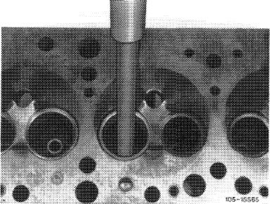
3 Force-out valve guide by means of knock-out mandrel.
4 Check basic bore in cylinder head for score marks.
Normally dimensioned valve guides can be inserted without machining basic bore, if the specified overlap is still available (refer to item 6).
|
 |
|||
|
|
||||
|
05.8-285/2 F 2
|
||||
|
|
||||
|
|
|||
|
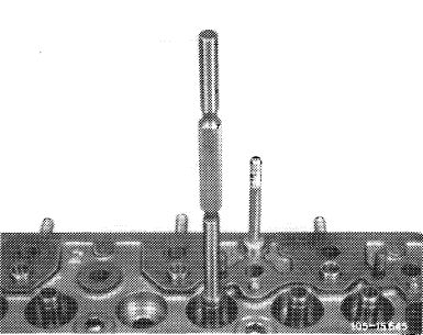
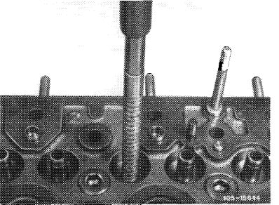
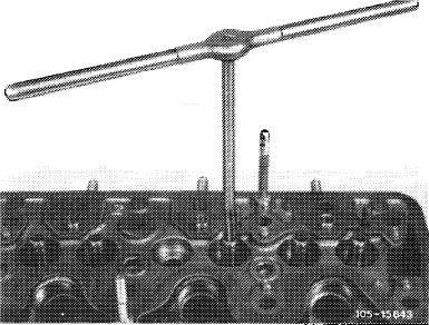
5 When using repair stage valve guides, press respective manual broach through basic bore in cylinder head.
Pressing of manual broach through basic bore can be performed on a column-type drilling machine or a hydraulic press. An important requirement is that the hand broach is inserted vertically in relation to base of cylinder head. The spindle of the column-type drilling machine or of the hydraulic press should be free of play.
|
 |
||
|
|
|||
|
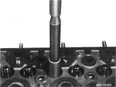
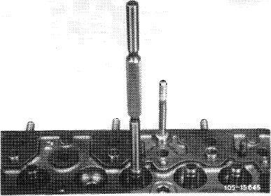
6 Coat valve guides with tallow and press-in by means of knocking-in mandrel until the dimension between cylinder head parting surface and valve guide underside named on table has been attained.
|
 |
||
|
|
|||
|
7 Check tight fit of valve guide with cylinder head cooled down only.
Test pressure of tight fit 3500 N.
|
 |
||
|
|
|||
|
8 Check ID of valve guide with plug gage.
|
|||
|
|
|||
|
The go end should still slip in.
|
 |
||
|
The not go end should merely touch.
|
|||
|
|
|||
|
05.8-285/3 F 2
|
|||
|
|
|||
|
|
|||
|
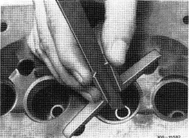
9 Slide valve into valve guide.
If the valve can be slipped in with difficutly only or not at all, ream valve guide by means of reamer.
10 Machine (refinish) valve seats (05—291).
|
 |
||
|
|
|||
|
05.8-285/4 F 2
|
|||
|
|
|||