Removal and installation of chain tensioner
|
|
|||||||||||||||||||||||||||||||||||||||||||||||||||||||||||||||||
|
05—310 Removal and installation of chain tensioner
|
|||||||||||||||||||||||||||||||||||||||||||||||||||||||||||||||||
|
|
|||||||||||||||||||||||||||||||||||||||||||||||||||||||||||||||||
|
|||||||||||||||||||||||||||||||||||||||||||||||||||||||||||||||||
|
|
|||||||||||||||||||||||||||||||||||||||||||||||||||||||||||||||||
|
Note
|
|||||||||||||||||||||||||||||||||||||||||||||||||||||||||||||||||
|
|
|||||||||||||||||||||||||||||||||||||||||||||||||||||||||||||||||
|
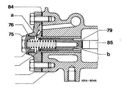
This engine is provided with a hydraulic detent chain tensioner without valve.
The pressure required for tensioning timing chain comprises the force of the compression spring (77) and the oil pressure in chain tensioner, in dependence of engine oil pressure.
|
|||||||||||||||||||||||||||||||||||||||||||||||||||||||||||||||||
|
|
|||||||||||||||||||||||||||||||||||||||||||||||||||||||||||||||||
|
In the event of shock-type loads, a throttle bore (a) of 1.5 mm dia. in oil feed and a throttle bore (b) of 1.3 mm dia. in thrust bolt prevents fast flowing-off of oil.
|
 |
||||||||||||||||||||||||||||||||||||||||||||||||||||||||||||||||
|
|||||||||||||||||||||||||||||||||||||||||||||||||||||||||||||||||
|
|
|||||||||||||||||||||||||||||||||||||||||||||||||||||||||||||||||
|
The chain tensioner housing (83) holds a detent and on pressure bolt (79) a detent spring (78).
The pressure bolt moves forward from detent to detent in accordance with elongation of chain. Travel to the rear is limited by detents. As a result, the pressure bolt cannot be pushed back when the engine is stopped. Any jumping of the loose timing chain or any chain noise when the engine is started is therefore eliminated.
|
|||||||||||||||||||||||||||||||||||||||||||||||||||||||||||||||||
|
|
|||||||||||||||||||||||||||||||||||||||||||||||||||||||||||||||||
|
05.8-310/1 F2
|
|||||||||||||||||||||||||||||||||||||||||||||||||||||||||||||||||
|
|
|||||||||||||||||||||||||||||||||||||||||||||||||||||||||||||||||
|
|
|||
|
The oil required for operation of chain tensioner is provided via first camshaft bearing, the cylinder head bolt bore at front right and a transverse duct in cylinder head.
During assembly and test jobs on chain drive, the chain tensioner need not be removed. In such cases it will be enough to remove the compression spring (77) (item 3, 4, 11 and 12).
|
|||
|
|
|||
|
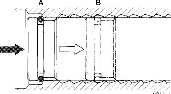
If, on the other hand, parts of the chain drive are renewed, remove chain tensioner and set pressure bolt into assembly position.
When installing a new chain tensioner, also pay attention to assembly position (A). If the pressure bolt is too far forward (in last detent), the timing chain is extensively tensioned or the detent spring (78) is stuck in detent.
|
 |
||
|
A Chain tensioner in assembly position B Chain tensioner in operating position
|
|||
|
|
|||
|
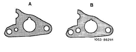
On engine 617.950 starting with engine end No. 006223, the chain tensioner gasket (B) has been installed for reasons of standardization with engines 615, 616 and 617.912. On engines 617.951/952 from start of series.
|
 |
||
|
A 1st version B 2nd version
|
|||
|
|
|||
|
Removal
|
 |
||
|
1 Drain coolant.
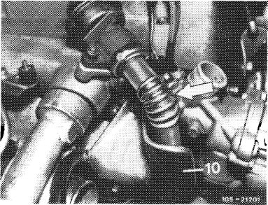
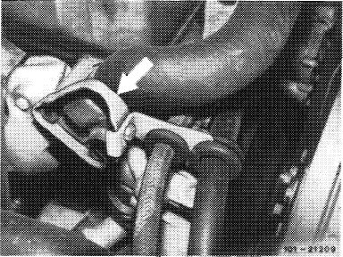
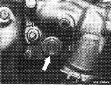
2 On engines with EGR <@), remove pipe line between EGR valve and exhaust manifold (arrow). For this purpose, unscrew shielding plate (10).
|
|||
|
|
|||
|
05.8-310/2 F2
|
|||
|
|
|||
|
|
|||
|
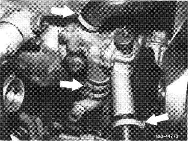
3 On model 123 with level control, unscrew line holder on thermostat housing (arrow).
|
 |
||
|
|
|||
|
4 Remove thermostat housing.
|
 |
||
|
|
|||
|
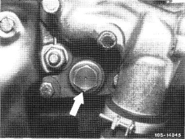
5 Unscrew closing plug (75) of chain tensioner.
Attention!
Closing plug is under pressure of compression spring (77).
|
 |
||
|
|
|||
|
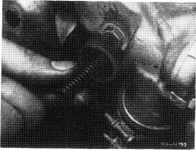
6 Remove compression spring (77).
|
 |
||
|
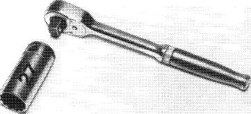
7 Unscrew chain tensioner housing and pull out.
|
|||
|
|
|||
|
05.8-310/3 F 2
|
|||
|
|
|||
|
|
|||
|
8 Pull out pressure bolt (79) in forward direction.
9 Thoroughly clean all parts.
|
 |
||
|
|
|||
|
Installation
|
|||
|
|
|||
|
Note: Prior to installing chain tensioner, the chain drive must be completely mounted.
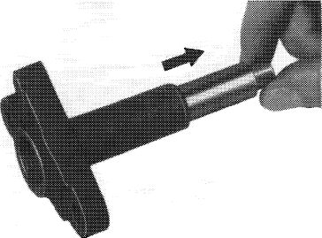
10 Rotate engine with tool combination in direction, of rotation once, so that timing chain is under tension.
|
 |
||
|
|
|||
|
11 Insert chain tensioner housing (83) with new gasket (84) and tighten.
|
|||
|
|
|||
|
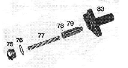
75 Closing plug
76 Sealing ring
77 Compression spring
78 Detent spring
79 Pressure bolt
83 Chain tensioner housing
|
 |
||
|
|
|||
|
12 Place pressure bolt (79) on assembly detent.
13 Insert compression spring (77).
14 Position closing plug (75) with new sealing ring (76) and tighten to 90 Nm.
|
 |
||
|
15 For further installation proceed vice versa to removal.
|
|||
|
|
|||
|
05.8-310/4 F2
|
|||
|
|
|||