Inspection and adjustment of valve clearance
|
|
|||||||||||||||||||||||||||
|
05—210 Inspection and adjustment of valve clearance
|
|||||||||||||||||||||||||||
|
|
|||||||||||||||||||||||||||
|
Valve clearance
|
with engine cold (approx. 20 °C) with engine warm (60 °C ± 15 °C)
|
||||||||||||||||||||||||||
|
|
|||||||||||||||||||||||||||
|
Intake
|
0.101;
|
0.151!
|
|||||||||||||||||||||||||
|
|
|||||||||||||||||||||||||||
|
Exhaust
|
0.35
|
0.40
|
|||||||||||||||||||||||||
|
|
|||||||||||||||||||||||||||
|
1) 0.05 mm higher during lasting outside temperatures below —20 °C.
|
|||||||||||||||||||||||||||
|
|
|||||||||||||||||||||||||||
|
|||||||||||||||||||||||||||
|
|
|||||||||||||||||||||||||||
|
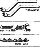
Valve adjusting wrench 14 mm (2 each)
|
 |
615 589 00 01 00
|
|||||||||||||||||||||||||
|
Holding wrench for valve spring retainer
|
615 589 00 03 00
|
||||||||||||||||||||||||||
|
Slip gage holder, red
|
617 589 00 40 00
|
||||||||||||||||||||||||||
|
|
|||||||||||||||||||||||||||
|
Slip gage blades
|
0.10 mm thick 0.15 mm thick 0.20 mm thick 0.35 mm thick 0.40 mm thick
|
 |
617 589 00 23 00 617 589 01 23 00 117 589 00 23 00 617 589 03 23 00 617 589 04 23 00
|
||||||||||||||||||||||||
|
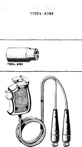
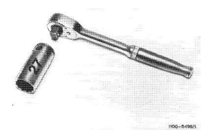
Socket 27 mm, 1/2″ square for rotating engine
|
001 589 65 09 00
|
||||||||||||||||||||||||||
|
Contact handle for rotating engine (component of compression pressure recorder 001 589 46 21 00)
|
001 589 46 21 08
|
||||||||||||||||||||||||||
|
11004-8*87
|
|||||||||||||||||||||||||||
|
|
|||||||||||||||||||||||||||
|
Note
|
 |
||||||||||||||||||||||||||
|
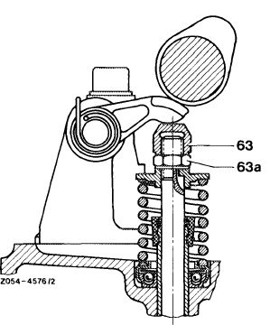
Check valve clearance with engine cold or warm and adjust, if required.
During adjustment, check cap nut and counternut for tight seat and wear.
|
|||||||||||||||||||||||||||
|
05.8-210/1 F2
|
63 Cap nut 63a Counternut
|
||||||||||||||||||||||||||
|
|
|||||||||||||||||||||||||||
|
|
|||
|
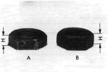
Also check valves which are not in need of adjustment.
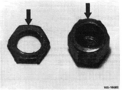
Renew cap nuts and counternuts in the following cases:
|
|||
|
|
|||
|
Height of counternut (A) below 5 mm (H). New counternuts (B) have a height of 6 mm.
|
 |
||
|
|
|||
|
Counterlocking surfaces of nuts badly worn (arrows).
In such cases, check threads on valve stem and also replace valves, if required.
|
 |
||
|
|
|||
|
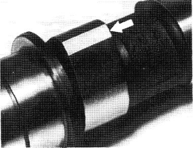
Check camshafts made of malleable iron (code number 00) for wear. Formation of excessive flats on cam (arrow) may result in loosening of counterlocked nuts. If flats show up, renew camshaft, rocker arm, valve springs, as well as cap nuts and counternuts. Also check valves and replace, if required.
|
105-14501
|
||
|
|
|||
|
05.8-210/2 F2
|
|||
|
|
|||
|
|
|||
|
On camshafts made of chilled cast iron (code number 05 and 08) a slight formation of flats is possible, but flats will not increase and are therefore technically insignificant.
|
|||
|
|
|||
|
Adjustment
|
 |
||
|
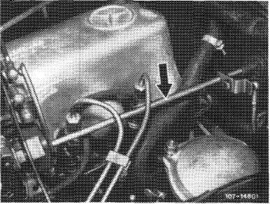
1 Disconnect regulating linkage to remove cylinder head cover. Pull out locking eye of longitudinal regulating shaft (arrow).
|
|||
|
Model 126.120
|
|||
|
|
|||
|
On models 116.120 and 123, pull longitudinal regulating shaft out of rubber mount in forward direction and remove in rearward direction.
|
 |
||
|
Model 123
|
|||
|
|
|||
|
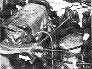
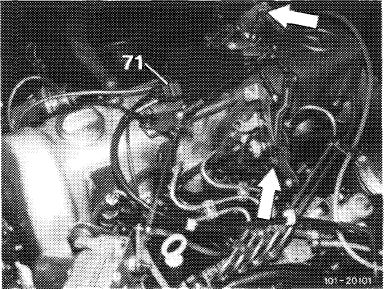
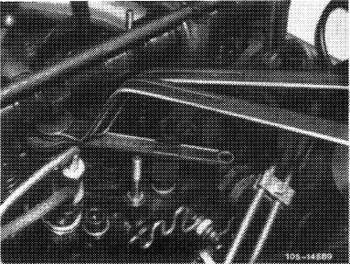
On models 123 with automatic transmission 722.303 (W 4 A 040) and 126.120, pull off central plug for vacuum lines (71) or vacuum lines. Disconnect Bowden wire, compress black plastic clip (arrow) and pull Bowden wire out of holder in rearward direction.
|
 |
||
|
Model 126.120
|
|||
|
|
|||
|
05.8-210/3 F2
|
|||
|
|
|||
|
|
||||
|
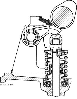
2 Check valve clearance between slide surface of rocker arm and cam base circle of camshaft (arrow). Tip of cam should be vertical in relation to rocker arm.
Valve clearance is correctly set when pulling of slip gage blade requires some effort.
|
 |
|||
|
|
||||
|
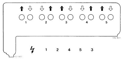
Observe layout of intake and exhaust valves.
|
 |
|||
|
U Intake Exhaust
|
||||
|
|
||||
|
The engine can be rotated as follows:
a) With tool combination at crankshaft front
Attention!
Do not rotate engine at fastening bolt of camshaft sprocket
Do not rotate crankshaft in reverse.
|
 |
|||
|
|
||||
|
b) With starter motor and contact handle
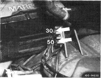
Connect contact handle to cable connector, terminal 30 and 50.
The cable connector is located at the following points:
Model 116.120: Under battery.
|
 |
|||
|
Model 116.120
|
||||
|
|
||||
|
05.8-210/4 F 2
|
||||
|
|
||||
|
|
||||
|
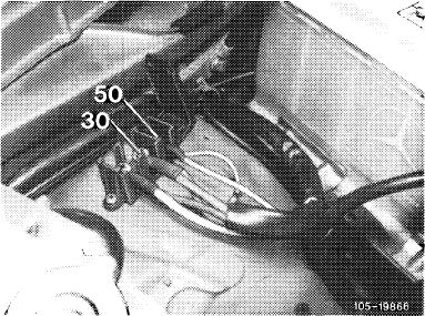
Model 123: At right on wheel house.
|
Model 123
|
 |
||
|
|
||||
|
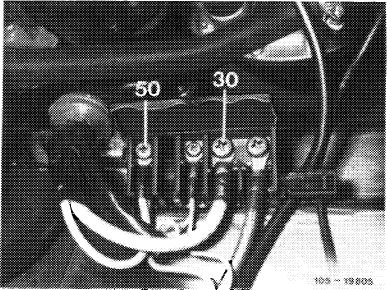
Model 126.120: On frame side member.
|
 |
|||
|
Model 126.120
|
||||
|
|
||||
|
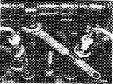
3 Place holding wrench on valve spring retainer.
|
 |
|||
|
|
||||
|
4 Loosen cap nut while applying counterhold to counternut on valve by means of valve adjusting wrench.
5 Adjust valve clearance by turning cap nut.
6 Following adjustment, secure cap nut with counternut (torque reference value 20—30 Nm).
7 Check valve clearance once again.
|
 |
|||
|
|
||||
|
05.8-210/5 F2
|
||||
|
|
||||