Checking choke system
|
|
|||||||||||||||||||||||||||||||||||
|
07.3-125 Checking choke system
|
|||||||||||||||||||||||||||||||||||
|
|
|||||||||||||||||||||||||||||||||||
|
Test values in bar gauge pressure
|
|||||||||||||||||||||||||||||||||||
|
|
|||||||||||||||||||||||||||||||||||
|
|||||||||||||||||||||||||||||||||||
|
|
|||||||||||||||||||||||||||||||||||
|
Control pressure according to ambient temperature at idle with engine cold
|
min. 0.5
(refer to diagram)
|
||||||||||||||||||||||||||||||||||
|
|
|||||||||||||||||||||||||||||||||||
|
Starting voltage
|
10 V
|
||||||||||||||||||||||||||||||||||
|
|
|||||||||||||||||||||||||||||||||||
|
) If the control pressure is not attained, check intake manifold vacuum (section „Checking control pressure at idle with engine at operating temperature”).
|
|||||||||||||||||||||||||||||||||||
|
|
|||||||||||||||||||||||||||||||||||
|
Special tool
|
|||||||||||||||||||||||||||||||||||
|
|
|||||||||||||||||||||||||||||||||||
|
Pressure measuring device
|
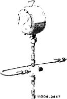 |
102 589 00 21 00
|
|||||||||||||||||||||||||||||||||
|
|
|||||||||||||||||||||||||||||||||||
|
Conventional tools
|
|||||||||||||||||||||||||||||||||||
|
|
|||||||||||||||||||||||||||||||||||
|
Voltmeter and ohmmeter
|
|||||||||||||||||||||||||||||||||||
|
|
|||||||||||||||||||||||||||||||||||
|
Revolution counter
|
|||||||||||||||||||||||||||||||||||
|
|
|||||||||||||||||||||||||||||||||||
|
Checking
|
|||||||||||||||||||||||||||||||||||
|
|
|||||||||||||||||||||||||||||||||||
|
1 Pull cable plug from warm-up compensator and from cold starting valve.
|
|||||||||||||||||||||||||||||||||||
|
|
|||||||||||||||||||||||||||||||||||
|
07.3.2 I la—1 25/1
|
F 2
|
||||||||||||||||||||||||||||||||||
|
|
|||||||||||||||||||||||||||||||||||
|
|
||||
|
2 Checking starting voltage.
Pull plug from ignition transmitter on switching unit (green cable) or plug protective plug, part no. 102 589 02 21 00, on diagnosis socket.
Operate starter for a short moment while reading voltage. Nominal value min. 10 Volts. If nominal value is not attained, test battery, charge or replace, if required.
3 Check air flow sensor plate and control piston for easy operation, check fuel pressures and for internal leaks, as well as stabilizing time of warm-up compensator (07.3-120).
Checking cold-starting valve for function and leaks
|
 |
|||
 |
||||
|
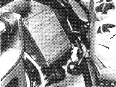
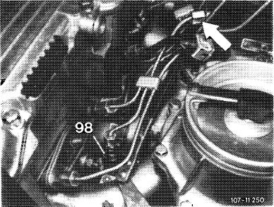
4 Unscrew fuel line on cold-starting valve (98) and remove cold-starting valve.
5 Loosen fuel line (arrow) on fuel distributor and turn in such a manner that the cold starting valve can be again connected. Then hold cold starting valve into a container.
|
||||
|
|
||||
|
Checking function
6 Switch-on ignition.
7 Connect cold starting valve with separate cable to B + and ground. Cold starting valve should eject in shape of cone.
Attention!
Connect cable first to cold starting valve so that no sparking occurs.
No separate cable need be used below +15 °C, plug-on cable plug instead and pull cable plug from safety switch.
|
||||
|
|
||||
|
Checking for leaks
8 Loosen separate cable connection on cold starting valve. Dry cold starting valve on nozzle. No drops should form.
9 Switch off ignition.
10 Mount cold starting valve with new seal.
11 Plug cable plug on safety switch and on cold-starting valve again.
|
||||
|
|
||||
|
07.3.2 I la—1 25/2
|
F 2
|
|||
|
|
||||
|
|
||||
|
Testing thermo time switch
|
 |
|||
|
The cold starting valve is actuated by closed thermo time switch only at coolant temperatures below + 15°C.
The actuating time increases with decreasing temperature and attains approx. 12 seconds at —20 °C.
|
||||
|
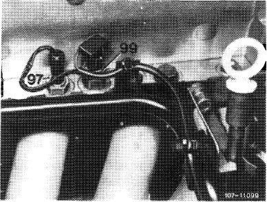
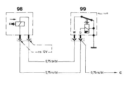
99 Thermo time switch
|
||||
|
|
||||
|
Testing below +15 °C coolant temperature
|
||||
|
|
||||
|
12 Connect voltmeter to connection of cold starting valve.
13 Actuate starter. Depending on coolant temperature, voltmeter should then indicate 10 Volts for a given period.
The switching time increases with decreasing temperature by approx. 1.5 seconds per 5 °C.
e.g. + 15 °C =0 seconds + 10 °C= 1.5 seconds
It is recommended to test thermo time switch additionally with an ohmmeter for this test.
Test value below+15 °C:
Connection G-ground = approx. 48 12 Connection W-ground = approx. 012
(Contacts in switch closed).
|
||||
|
|
||||
|
Testing above +15 °C coolant temperature
|
||||
|
|
||||
|
Above +15 °C coolant temperature the thermo time switch can be tested only by means of an ohmmeter. For this purpose, pull plug from thermo time switch.
Test values above +15 °C:
Connection G-ground = approx. 62 12 Connection W-ground = approx. 270 12
(Contacts in switch open). Re-attach plug.
|
 |
|||
|
07.3.2 I la—1 25/3 F2
|
98 Cold starting valve
99 Thermo time switch c To terminal 50
|
|||
|
|
||||
|
|
||
|
Testing cutoff point of auxiliary air valve
|
||
|
|
||
|
14 Following a cold start, the engine speed should amount to approx. 800—1000/min. The speed will then increase to approx. 1 200—1300/min, and will drop to normal idle speed at approx. 70 °C.
15 Stop engine. Disconnect pressure measuring device while catching fuel with a rag.
16 Connect fuel lines, run engine once again and check all fuel connections for leaks.
|
||
|
|
||
|
07.3.2 I la —1 25/4 F2
|
||
|
|
||