Removal and installation of rear engine mount
|
|
||||||||||||||||||||||||||||||||||||||||||||||||||||||||||
|
22—212 Removal and installation of rear engine mount
|
||||||||||||||||||||||||||||||||||||||||||||||||||||||||||
|
|
||||||||||||||||||||||||||||||||||||||||||||||||||||||||||
|
Model 107
|
||||||||||||||||||||||||||||||||||||||||||||||||||||||||||
|
|
||||||||||||||||||||||||||||||||||||||||||||||||||||||||||
|
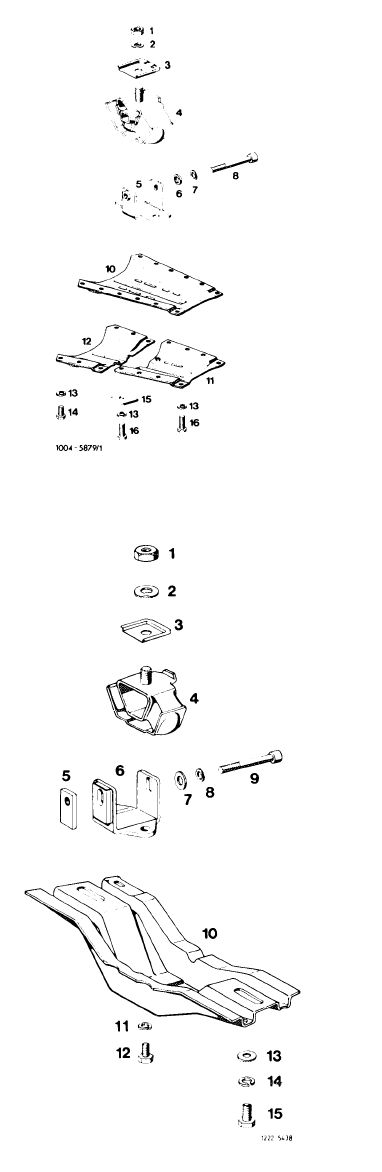
Attention!
For removal of engine mount (4) do not unscrew closing plate (10 or 12).
Attach engine mount free of tension to closing plate.
After installing engine mount, run engine at idle for a short period with adjusting screw released. With engine stopped, tighten adjusting screw (8) to 40 Nm.
Attention!
Check regulating linkage for function.
|
 |
|||||||||||||||||||||||||||||||||||||||||||||||||||||||||
|
||||||||||||||||||||||||||||||||||||||||||||||||||||||||||
|
8 Adjusting screw M 8×75 16 Screw M 8 x 32
|
||||||||||||||||||||||||||||||||||||||||||||||||||||||||||
|
Model 114
|
||||||||||||||||||||||||||||||||||||||||||||||||||||||||||
|
Mote: The engine mount for automatic transmission and for 5-speed transmission is provided with a stop.
For removing engine mount (4), do not unscrew engine carrier (10).
Following installation of engine mount, run engine for a short period at idle with adjusting screw (9) released. With engine stopped, tighten adjusting screw (9) to 40 Nm.
Attention!
Shims between engine carrier and frame floor are decisive for alignment of propeller shafts and should be added again at the same spot.
|
||||||||||||||||||||||||||||||||||||||||||||||||||||||||||
|
||||||||||||||||||||||||||||||||||||||||||||||||||||||||||
|
|
||||||||||||||||||||||||||||||||||||||||||||||||||||||||||
|
|
|||||||||||||||||||||||||||||||||||||||||||||||||||||||||||||||||||||
|
Model 116
|
 |
||||||||||||||||||||||||||||||||||||||||||||||||||||||||||||||||||||
|
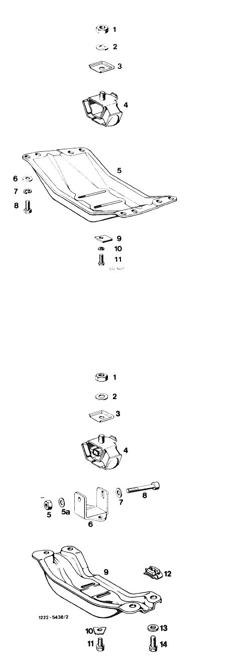
Attention!
For removal of engine mount (4) do not unscrew engine carrier (5).
Attach engine mount free of tension to engine carrier.
|
|||||||||||||||||||||||||||||||||||||||||||||||||||||||||||||||||||||
|
1 NutM12x1.5
2 Spring washer
3 Holding plate
4 Engine mount
5 Engine carrier
6 Washer 8.4
|
|
||||||||||||||||||||||||||||||||||||||||||||||||||||||||||||||||||||
|
Model 123
|
|||||||||||||||||||||||||||||||||||||||||||||||||||||||||||||||||||||
|
Attention!
For removal of engine mount (4) do not unscrew engine carrier (9).
Upon installation of engine mount run engine at idle for a short period with adjusting screw released.
With engine stopped, tighten adjusting screw (8) to 40 Nm.
|
|||||||||||||||||||||||||||||||||||||||||||||||||||||||||||||||||||||
|
|||||||||||||||||||||||||||||||||||||||||||||||||||||||||||||||||||||
|
|
|||||||||||||||||||||||||||||||||||||||||||||||||||||||||||||||||||||
|
22.2-212/2 F3
|
|||||||||||||||||||||||||||||||||||||||||||||||||||||||||||||||||||||
|
|
|||||||||||||||||||||||||||||||||||||||||||||||||||||||||||||||||||||
|
|
||||||||||||||||||||||||||||||||||||||||||||||||||||||||||||||||||||||||||||
|
Model 126
|
||||||||||||||||||||||||||||||||||||||||||||||||||||||||||||||||||||||||||||
|
|
||||||||||||||||||||||||||||||||||||||||||||||||||||||||||||||||||||||||||||
|
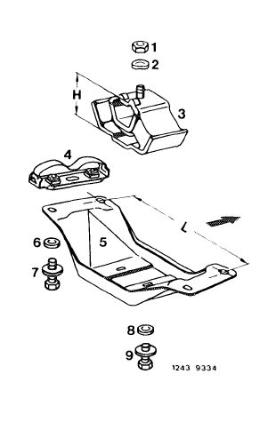
Attention!
To remove engine mount (3) do not unscrew engine carrier (5).
Engine mount (3) and engine carrier (5) are different for manual and automatic transmission.
|
||||||||||||||||||||||||||||||||||||||||||||||||||||||||||||||||||||||||||||
|
|
||||||||||||||||||||||||||||||||||||||||||||||||||||||||||||||||||||||||||||
|
Differences:
Transmission Engine mount Engine carrier
|
manual
H = 62-64 mm
L = 356 mm
|
automatic
H – 67-69 mm
L = 301 mm
|
 |
|||||||||||||||||||||||||||||||||||||||||||||||||||||||||||||||||||||||||
|
When installing engine mount (3) attach free of tension to engine carrier (5) with oblong holes by means of screws (9).
|
||||||||||||||||||||||||||||||||||||||||||||||||||||||||||||||||||||||||||||
|
||||||||||||||||||||||||||||||||||||||||||||||||||||||||||||||||||||||||||||
|
|
||||||||||||||||||||||||||||||||||||||||||||||||||||||||||||||||||||||||||||
|
22.2-212/3 F3
|
||||||||||||||||||||||||||||||||||||||||||||||||||||||||||||||||||||||||||||
|
|
||||||||||||||||||||||||||||||||||||||||||||||||||||||||||||||||||||||||||||