Removal and installation of engine shock absorber
|
|
||||
|
22—240 Removal and installation of engine shock absorber
|
||||
|
|
||||
|
Model 107, engine shock absorber left and right
1 For removing righthand engine shock absorber, remove expansion tank.
2 For removing lefthand engine shock absorber, remove pressure regulator (injection engine).
3 Unscrew screw for attaching engine from engine mount and engine shock absorber.
4 Remove engine shock absorber together with holder.
Attention!
During installation, pay attention to position of rubber buffers and cup springs (22—211).
On USA vehicles starting model year 1975, use the upper rubber buffers made of heat-resistant material.
|
 |
|||
|
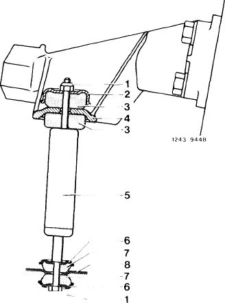
Engine shock absorber right, seen from the front
|
||||
|
1 Cup spring 30 mm dia.
2 Rubber buffer 26 mm dia.
3 Cup spring 26 mm dia.
|
4 Cup spring 32 mm dia.
5 Cup spring 26 mm dia.
6 Rubber buffer 22 mm dia.
|
|||
|
|
||||
|
22.2-240/1 F3
|
||||
|
|
||||
|
|
||||||||
|
Model 114, engine shock absorber right
On engines with air conditioning, remove radiator and vibration damper (03—340) for removal of righthand engine shock absorber with holder.
On engines without air conditioning, remove alternator with holder and carrier for removing righthand engine shock absorber.
Attention!
During installation, pay attention to position of rubber buffer and cup springs.
|
 |
|||||||
|
Engine shock absorber right, seen from the front
|
26 mm dia. 22 mm dia. 110241 02 02
26 mm dia. 22 mm dia. 110 241 03 02
|
|||||||
|
1st version L
1 Cup spring
2 Rubber buffer
|
= 28 mm 26 mm dia. 22 mm dia.
|
3 Cup spring
4 Rubber buffer
5 Holder part no.
3 Cup spring
4 Rubber buffer
5 Holder part no.
|
||||||
|
2nd version L =34 mm
1 Cup spring 31 mm dia.
2 Rubber buffer 26 mm dia.
|
||||||||
|
|
||||||||
|
Model 114, engine shock absorber left
|
 |
|||||||
|
1 Unscrew screw from engine mount. Loosen engine shock absorber at top.
2 Remove engine shock absorber together with holder.
Attention!
During installation, pay attention to position of rubber buffers and cup springs.
|
||||||||
|
Engine shock absorber left, seen from the front L = 34 mm
|
||||||||
|
1 Cup spring
2 Rubber buffer
3 Cup washer
4 Rubber buffer
|
108 241 00 12 123 241 03 65 115 241 08 12 107 241 00 65
|
26 mm dia. 26 mm dia. 31 mm dia. 22 mm dia.
|
||||||
|
|
||||||||
|
22.2-240/2 F3
|
||||||||
|
|
||||||||
|
|
|||
|
Model 116, engine shock absorber left and right
During installation, pay attention to position of rubber buffers and cup springs.
On USA vehicles starting model year 1975, use the two upper rubber buffers part no. 115 241 17 65.
Engine shock absorber and layout are similar at the left and right.
|
 |
||
|
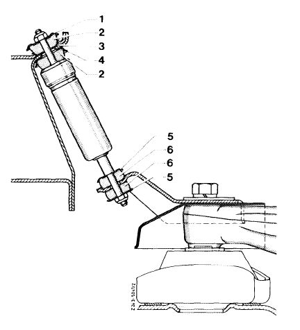
Engine shock absorber right, seen from the front
L = 34 mm
1 Cup spring 30 mm dia.
2 Rubber buffer 26 mm dia.
3 Cup spring 26 mm dia.
4 Rubber buffer 32 mm dia.
|
|||
 |
|||
|
|
|||
|
Model 123, engine shock absorber left and right
|
1003-7143
|
||
|
During installation, pay attention to position of rubber buffers and cup springs.
Engine shock absorber and layout are similar at left and right.
|
|||
|
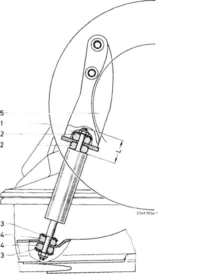
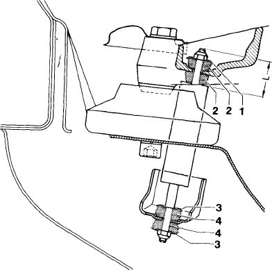
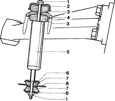
Engine shock absorber left, seen from the rear
1 Nut
2 Cup spring 44 mm dia.
3 Rubber buffer 36 mm dia.
4 Engine carrier
5 Engine shock absorber
6 Cup spring 30 mm dia.
7 Rubber buffer 27 mm dia.
|
|||
|
|
|||
|
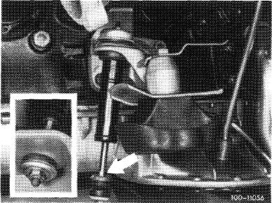
Attention!
For removal and installation of engine shock absorber, hold piston rod in position at flat provided (arrow).
|
 |
||
|
|
|||
|
22.2-240/3 F3
|
|||
|
|
|||
|
|
|||
|
Model 126, engine shock absorber left and right
During installation, pay attention to position of rubber buffers and cup springs.
Engine shock absorber and layout are similar at left and right.
|
tot
|
||
|
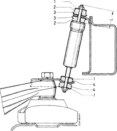
Engine shock absorber right seen from the front
|
|||
|
|
|||
|
22.2-240/4 F3
|
|||
|
|
|||