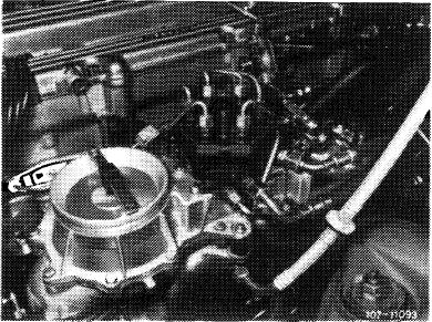
Removal and installation of mixture controller with air guide housing
|
|
|||||
|
07.3—225 Removal and installation of mixture controller with air guide housing
|
|||||
|
|
|||||
|
Tightening torques
|
Nm
|
||||
|
|
|||||
|
Hex. nuts mixture controller to intake manifold (rubber buffer)
|
9-10
|
||||
|
|
|||||
|
Injection lines and fuel lines to fuel distributor (reference value)
|
10-12
|
||||
|
|
|||||
|
Injection lines to injection valves (reference value)
|
10-15
|
||||
|
|
|||||
|
Special tool
|
|||||
|
|
|||||
|
Torque wrench 1/4″ square, 4—16 Nm
|
 |
000 589 67 21 00
|
|||
|
|
|||||
|
Removal
|
 |
||||
|
1 Remove air cleaner.
2 Unscrew all fuel and injection lines on fuel distributor and on injection valves. Catch fuel with a rag.
Close fuel feed and return flow line blind.
3 Pull electric connecting cables, to the extent installed, from safety switch.
4 Loosen hose clamp on rubber sleeve between air guide housing and throttle valve housing.
5 Unscrew both hex. nuts on rubber buffers.
6 Lift off mixture controller with air guide housing, while pulling off idle air hose.
|
|||||
|
|
|||||
|
07.3.2 Ma—225/1 F2
|
|||||
|
|
|||||
|
|
||
|
Installation
|
||
|
|
||
|
7 For installation proceed vice versa.
8 Tighten both hex. nuts to specified tightening torques by means of a torque wrench.
9 Connect injection lines and fuel lines, while paying attention to tightening torques as reference values.
Attention!
When tightening injection lines and fuel lines, apply counterhold to injection valves as well as to double thread connections on fuel distributor.
10 Run engine and check all fuel connections for leaks.
11 Adjust idle speed (07.3-100).
|
||
|
|
||
|
07.3.2 lla-225/2 F2
|
||
|
|
||