Removal and installation of fuel pump
|
|
|||||
|
07.3—280 Removal and installation of fuel pump
|
|||||
|
|
|||||
|
Special tools
|
|||||
|
|
|||||
|
Clamp for hose lines
|
 |
000 589 40 37 00
|
|||
|
|
|||||
|
Note
|
 |
||||
|
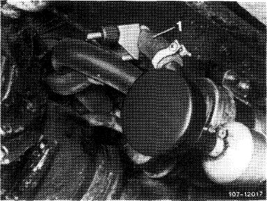
The fuel pump is provided with a special coating on roller running surface, an exchangeable check valve and, to prevent contact corrosion, a plastic sleeve.
The check valve has been moved in outward direction and can be separately replaced in the event of failure.
|
|||||
|
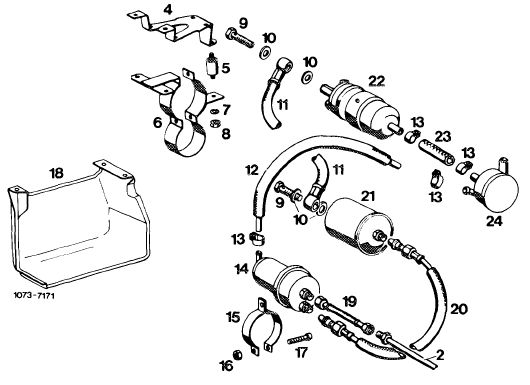
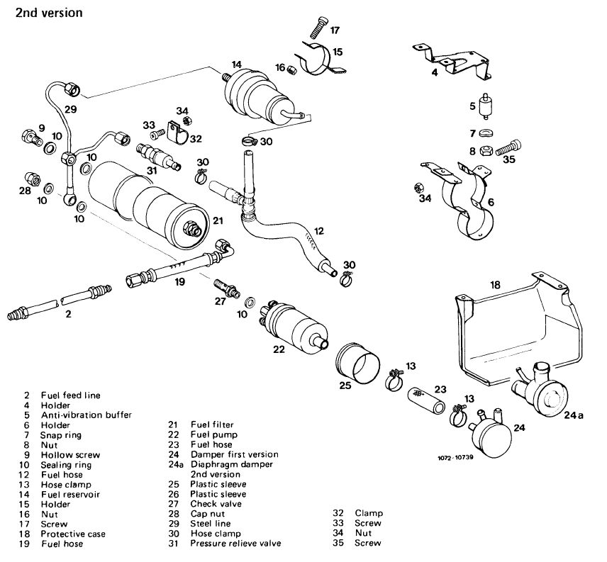
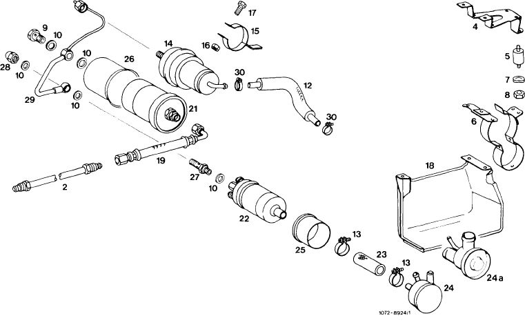
22 Fuel pump
32 Check valve
33 Sealing ring
|
|||||
|
|
|||||
|
When exchanging fuel pump, make sure that the plastic sleeve is mounted in-between fuel pump and holder. Sleeve should project on both sides of holder, since direct contact of fuel pump with holder may lead to contact corrosion.
|
|||||
|
|
|||||
|
Removal
|
 |
||||
|
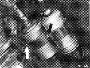
1 Unscrew protective case.
|
|||||
|
2 Pinch fuel suction hose (1) with a clamp.
|
|||||
|
|
|||||
|
07.3.2 I la-280/1 F2
|
|||||
|
|
|||||
|
|
|||
|
1st version
3 Loosen fuel hoses, pull off and unscrew.
4 Disconnect electric connecting cable.
5 Loosen fastening screw (arrow) and remove fuel pump.
|
 |
||
|
|
|||
|
2nd version
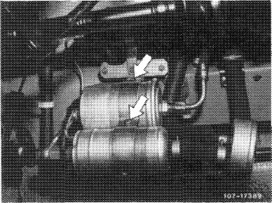
6 Loosen fuel line on fuel filter and fuel reservoir. Loosen fuel line on fuel pump, pull off and unscrew.
7 Disconnect electric connecting cable.
8 Loosen fastening screw (arrow) and remove fuel pump.
|
 |
||
|
|
|||
|
Installation
|
|||
|
|
|||
|
9 For installation proceed vice versa using new sealing rings.
Pay attention to perfect installation of fuel hoses, also to correct polarity. In installation position, terminals should be horizontal.
|
|||
|
|
|||
|
10 Locate fuel pump in holder by means of plastic sleeve. Plastic sleeve should project on both sides of holder, since direct contact of fuel pump with holder may lead to contact corrosion.
11 Remove clamp on fuel suction hose.
12 Run engine and check for leaks.
13 Mount protective case.
|
 |
||
|
|
|||
|
07.3.2 I la-280/2 F2
|
|||
|
|
|||
|
|
|||||||||||||||||||||||||||||||||||||||||||||||||||||||||||||||||||||||||||||||||||||||||||||||||||
|
1st version
|
|||||||||||||||||||||||||||||||||||||||||||||||||||||||||||||||||||||||||||||||||||||||||||||||||||
|
|
|||||||||||||||||||||||||||||||||||||||||||||||||||||||||||||||||||||||||||||||||||||||||||||||||||
|
 |
||||||||||||||||||||||||||||||||||||||||||||||||||||||||||||||||||||||||||||||||||||||||||||||||||
|
|
|||||||||||||||||||||||||||||||||||||||||||||||||||||||||||||||||||||||||||||||||||||||||||||||||||
 |
|||||||||||||||||||||||||||||||||||||||||||||||||||||||||||||||||||||||||||||||||||||||||||||||||||
|
|
|||||||||||||||||||||||||||||||||||||||||||||||||||||||||||||||||||||||||||||||||||||||||||||||||||
|
07.3.2 lla-280/3 F 2
|
|||||||||||||||||||||||||||||||||||||||||||||||||||||||||||||||||||||||||||||||||||||||||||||||||||
|
|
|||||||||||||||||||||||||||||||||||||||||||||||||||||||||||||||||||||||||||||||||||||||||||||||||||
|
|
|||||||||||||||||||||||||||||||||||||||||||||||||||||||||||||||||||||||||||||||||||||||||||||||||||
|
3rd version
|
|||||||||||||||||||||||||||||||||||||||||||||||||||||||||||||||||||||||||||||||||||||||||||||||||||
|
|
|||||||||||||||||||||||||||||||||||||||||||||||||||||||||||||||||||||||||||||||||||||||||||||||||||
 |
|||||||||||||||||||||||||||||||||||||||||||||||||||||||||||||||||||||||||||||||||||||||||||||||||||
|
|||||||||||||||||||||||||||||||||||||||||||||||||||||||||||||||||||||||||||||||||||||||||||||||||||
|
|
|||||||||||||||||||||||||||||||||||||||||||||||||||||||||||||||||||||||||||||||||||||||||||||||||||
|
07.3.2 lla-280/4
|
F 2
|
||||||||||||||||||||||||||||||||||||||||||||||||||||||||||||||||||||||||||||||||||||||||||||||||||
|
|
|||||||||||||||||||||||||||||||||||||||||||||||||||||||||||||||||||||||||||||||||||||||||||||||||||