Replacement of holder for fuel pump, fuel filter and fuel reservoir
|
|
|||||
|
07.3—281 Replacement of holder for fuel pump, fuel filter and fuel reservoir
|
|||||
|
|
|||||
|
For renewing holder, remove fuel reservoir (07.3-270), fuel filter (07.3-275), fuel pump (07.3-280).
|
|||||
|
|
|||||
|
Note
|
 |
||||
|
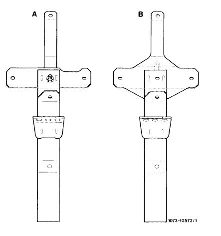
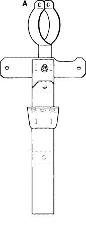
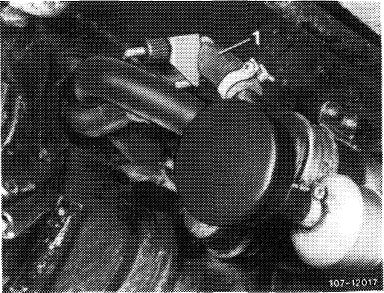
Holder has been modified to improve installation position and to increase rigidity.
|
|||||
|
Model 107, 123
A Former version
B Present version
|
|||||
|
|
|||||
|
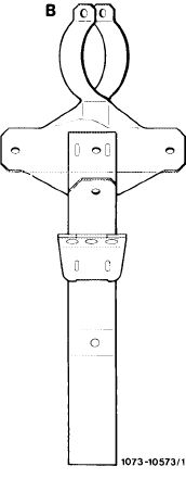
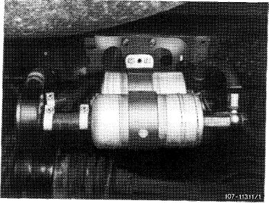
On model 126 the shape of the fuel line between pump, filter and reservoir has also been modified.
|
 |
 |
|||
|
Start of series production: November 1981.
|
|||||
|
Model 126
A Former version
B Present version
|
|||||
|
|
|||||
|
07.3.2 lla-281/1
|
F2
|
||||
|
|
|||||
|
|
||||
|
In front of fuel filter (21) is an additional pressure compensating valve (27), which closes in the event of pressure in system. If the fuel volume in system is reduced when the fuel is cooling down, the pressure compensating valve will open. This will prevent that the control piston in fuel distributor will be pulled to full load under influence of vacuum, since otherwise during a cold start the full fuel quantity might be injected for a short period and the engine might be excessively enriched.
|
 |
|||
|
|
||||
|
107-16158
|
||||
|
|
||||
|
B. Scope
|
 |
|||
|
Note
|
||||
|
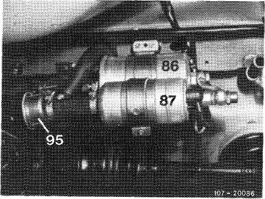
On models 107 and 126 fuel filters will be installed with damper (86), as well as a diaphragm damper (95). This will reduce noises caused by fuel pump.
|
||||
|
86 Fuel filter with damper
87 Fuel pump
95 Diaphragm damper
|
||||
|
|
||||
|
On vehicles in national version (*vs)(±y(j£) and(usA) with CIS injection system prior to model year 1981, the respective components can also be installed. On vehicles of model year 1981, the changes are already in place. However, the fuel pump assembly differs by a fuel filter of larger diameter (owing to revised maintenance intervals).
|
||||
|
|
||||
|
Introduction into series
|
||||
|
|
||||
|
Model
|
Starting chassis end no.
|
Remarks
|
||
|
|
||||
|
107.022 107.042
|
010166 010715
|
Fuel filter with damper and diaphragm damper (since April 1981)
Fuel filter with damper (since April 1980)
|
||
|
126.022/023
|
004661
|
|||
|
|
||||
|
126.022/023
|
016862
|
Diaphragm damper (since October 1980)
|
||
|
|
||||
|
On vehicles with lower chassis end no. the components can be subsequently installed in the event of complaints about „Fuel pump loud”.
|
||||
|
|
||||
|
07.3.2 I la-282/2 F2
|
||||
|
|
||||
|
|
||||
|
Special tool
|
||||
|
|
||||
|
Clamp for hose lines
|
 |
000 589 40 37 00
|
||
|
|
||||
|
Spare parts
|
||||
|
|
||||
|
Designation
|
Part no.
|
|||
|
|
||||
|
Conversion kit
Steel line for engines with light alloy fuel distributor
|
123 470 05 93 126 470 01 64
|
|||
|
|
||||
|
Responsible for delivery: Plant 50 (PEW Sindelfingen)
|
||||
|
|
||||
|
Note
|
 |
|||
|
When exchanging fuel filter (21), fuel pump (22) or pressure compensating valve (27) make sure that a plastic sheet or plastic sleeve is mounted between these parts and holder (6, 15, 28). Sleeve should project on both sides of holder, since direct contact of parts with holder may lead to contact corrosion.
On vehicles in (aus)and (T) version, a pressure compensating valve may not be subsequently installed.
|
||||
|
|
||||
|
07.3.2 I la-283/3 F2
|
||||
|
|
||||
|
|
||||
|
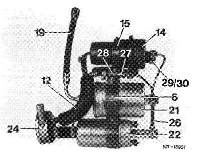
Layout fuel pump assembly
|
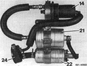
Former layout
14 Pressure reservoir
21 Filter
22 Fuel pump 24 Damper
|
 |
||
|
|
||||
|
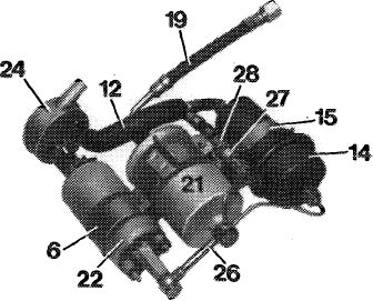
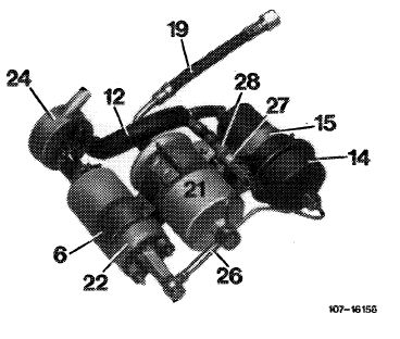
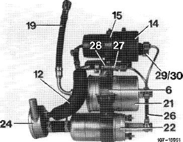
Present layout
6 Holder for fuel pump and filter 1 2 Leak line
14 Pressure reservoir w
15 Holder for pressure reservoir” 19 Fuel hose
21 Filter
22 Fuel pump
|
24 Damper
26 Fuel pressure line
27 Fuel compensating valve
28 Clamp for pressure compensating valve
29 Closing cone
30 Coupling nut
|
 |
||
|
|
||||
|
For conversion, the following parts may be used again:
Fuel pump, suction damper, pressure reservoir, fuel filter.
|
||||
|
|
||||
|
Conversion
|
 |
|||
|
1 Unscrew protective case.
2 Disconnect electric connections.
3 Pinch fuel suction hose (1) between fuel tank and suction damper by means of a clamp.
|
||||
|
|
||||
|
07.3..2 lla-282/4 F2
|
||||
|
|
||||
|
|
|||
|
4 Loosen suction hose on suction damper and pull off.
5 Unscrew fuel pressure line from feed line to engine compartment. Clean screw connection first.
6 Unscrew fastening nuts of anti-vibration buffers and remove „fuel pump assembly”.
7 Disassemble fuel pump assembly.
|
 |
||
|
|
|||
|
8 Clean fuel pump and fuel filter externally and mount in addition to plastic sleeve (slip up to bead of pump).
As an exception, a sheet (e.g. Tesafilm) may be glued on instead of plastic sleeve.
Attach plastic sleeve or sheet always in such a manner that it projects on both sides of holder. A direct contact of holder and pump or filter may lead to contact corrosion.
|
|||
|
|
|||
|
9 Assemble with components of conversion kit pump assembly, as shown in illustration. Slip fuel pump (22) up to bead into holder (6) and mount clamp (28) for pressure compensating valve (27) under holder of pressure reservojr. Prior to tightening screws of holder, position fuel pressure line (26) at pump, filter and pressure reservoir, align parts in relation to each other and tighten screws. On pressure reservoir, close the off-center connection with a closing cone (29) and a coupling nut (30).
|
 |
||
|
|
|||
|
10 Install pump assembly and fuel hoses, and make electrical connections.
11 Remove clamp on suction hose, run engine and check system for leaks.
12 Mount protective case. Then make sure that fuel hoses are not exposed to chafing.
Note: On vehicles with auxiliary heater, the leak line is approx. 50 mm in front of suction damper. Insert a T-fitting. Here, the protective anti-chafing hose must be shortened.
|
|||
|
|
|||
|
07.3.2 lla-282/5 F2
|
|||
|
|
|||