Oil circuit, oil pressure, pressure relief valves and oil filter
|
|
|||||
|
18—005 Oil circuit, oil pressure, pressure relief valves and oil filter
|
|||||
|
|
|||||
|
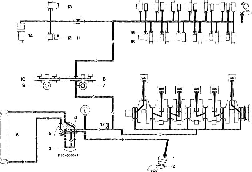
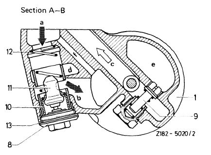
Oil circuit with air oil cooler
|
|||||
|
|
|||||
 |
|||||
|
|
|||||
|
1 Oil pump 5
2 Pressure relief valve (7 bar) (built-in oil pump) 6
3 Oil filter 7
4 Bypass valve filter element 8
|
Thermostat with 9
control valve 10 Air oil cooler
Oil pump drive 11
Intermediate wheel 12
shaft 13
|
Distributor drive 14
Intermediate wheel 15
shaft 16
Guide wheel 17 Intake camshaft Exhaust camshaft
|
Chain tensioner
Rocker arms
Camshaft bearings
Pressure relief valve
in front main oil bore (5 bar)
|
||
|
|
|||||
|
Attention!
The oil circuit is controlled by a thermostat (5) in the oil filter upper section.
Starting at an oil temperature of approx. 95 C or 110 °C (203 °F or 230 °F) beginning with model 126, the oil flows via air oil cooler. The bypass circuit is only opened as long os the oil temperature is below approx. 95 °C or 110 °C (203 °F or 230 °F).
If for any reason the air oil cooler (6) is disconnected or the connections on oil filter top are closed blind, removal of thermostat with control valve and compression spring is absolutely required (18—125). If this is not done, the oil supply to the bearing points will be interrupted at oil temperatures above approx. 95 °C or 110 °C (203 °F or 230 °F).
|
|||||
|
|
|||||
|
18.2-005/1 F3
|
|||||
|
|
|||||
|
|
||||||||||||||||||||||||||||||||||||||||||||||||||||||||||||
|
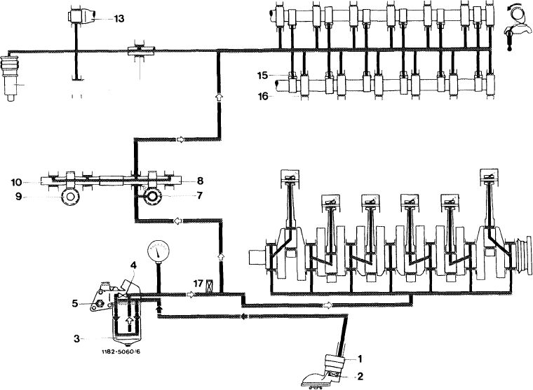
Oil circuit without air oil cooler
|
||||||||||||||||||||||||||||||||||||||||||||||||||||||||||||
|
|
||||||||||||||||||||||||||||||||||||||||||||||||||||||||||||
|
14 QD- 12 11
|
||||||||||||||||||||||||||||||||||||||||||||||||||||||||||||
|
|
||||||||||||||||||||||||||||||||||||||||||||||||||||||||||||
|
15 Rocker arms
16 Camshaft bearings
17 Pressure relief valve
in front main oil bore (5 bar)
|
|||||||||||||||||||||||||||||||||||||||||||||||||||||||||||
|
|
||||||||||||||||||||||||||||||||||||||||||||||||||||||||||||
|
Oil pressure
|
||||||||||||||||||||||||||||||||||||||||||||||||||||||||||||
|
|
||||||||||||||||||||||||||||||||||||||||||||||||||||||||||||
|
At operating temperature the oil pressure at idle may drop to 0.5 bar gauge pressure.
Upon acceleration the oil pressure should immediately increase again and should attain min. 3 bar gauge pressure at 3000 rpm.
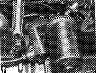
On model 126 the oil pressure is not indicated as before by means of a capillary tube connected to a pressure gauge in instrument cluster, but by means of a pressure transmitter which is electrically activated. The pressure transmitter is screwed to oil filter top (arrow).
|
 |
|||||||||||||||||||||||||||||||||||||||||||||||||||||||||||
|
Oil filter with pressure transmitter
|
||||||||||||||||||||||||||||||||||||||||||||||||||||||||||||
|
|
||||||||||||||||||||||||||||||||||||||||||||||||||||||||||||
|
18.2-005/2 F3
|
||||||||||||||||||||||||||||||||||||||||||||||||||||||||||||
|
|
||||||||||||||||||||||||||||||||||||||||||||||||||||||||||||
|
|
|||||||||||||||||||||||||||||||||||||||||||||||||||||||||||||||||||||||||||||||||||||||||||
|
Opening pressures of pressure relief and bypass valve
|
bar relief pressure
|
||||||||||||||||||||||||||||||||||||||||||||||||||||||||||||||||||||||||||||||||||||||||||
|
|
|||||||||||||||||||||||||||||||||||||||||||||||||||||||||||||||||||||||||||||||||||||||||||
|
Pressure relief valve (2) for oil pump
|
|||||||||||||||||||||||||||||||||||||||||||||||||||||||||||||||||||||||||||||||||||||||||||
|
|
|||||||||||||||||||||||||||||||||||||||||||||||||||||||||||||||||||||||||||||||||||||||||||
|
Bypass valve (4) for filter cartridge
|
3.5
|
||||||||||||||||||||||||||||||||||||||||||||||||||||||||||||||||||||||||||||||||||||||||||
|
|
|||||||||||||||||||||||||||||||||||||||||||||||||||||||||||||||||||||||||||||||||||||||||||
|
Pressure relief valve (17) in front main oil bore
|
|||||||||||||||||||||||||||||||||||||||||||||||||||||||||||||||||||||||||||||||||||||||||||
|
|
|||||||||||||||||||||||||||||||||||||||||||||||||||||||||||||||||||||||||||||||||||||||||||
|
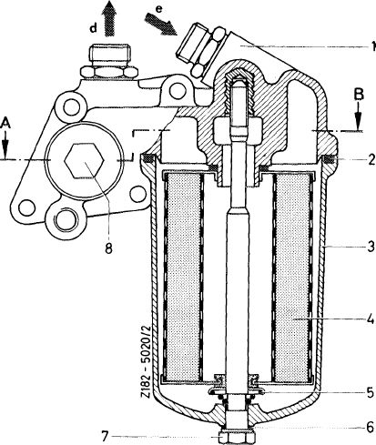
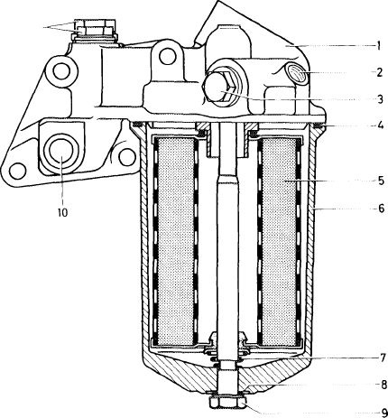
Oil filter models 107, 114, 116
|
 |
||||||||||||||||||||||||||||||||||||||||||||||||||||||||||||||||||||||||||||||||||||||||||
|
|
|||||||||||||||||||||||||||||||||||||||||||||||||||||||||||||||||||||||||||||||||||||||||||
|
 |
||||||||||||||||||||||||||||||||||||||||||||||||||||||||||||||||||||||||||||||||||||||||||
|
|
|||||||||||||||||||||||||||||||||||||||||||||||||||||||||||||||||||||||||||||||||||||||||||
|
18.2-005/3 F3
|
|||||||||||||||||||||||||||||||||||||||||||||||||||||||||||||||||||||||||||||||||||||||||||
|
|
|||||||||||||||||||||||||||||||||||||||||||||||||||||||||||||||||||||||||||||||||||||||||||
|
|
||||||||||||||||||||||||||||||||||||||||||||||||||||||||||||||||||||||||||||||||||||||||||||||||
|
Oil filter model 123 and models 107, 116 with continuous fuel injection, 2nd version carburetor engine
|
||||||||||||||||||||||||||||||||||||||||||||||||||||||||||||||||||||||||||||||||||||||||||||||||
|
|
||||||||||||||||||||||||||||||||||||||||||||||||||||||||||||||||||||||||||||||||||||||||||||||||
|
||||||||||||||||||||||||||||||||||||||||||||||||||||||||||||||||||||||||||||||||||||||||||||||||
|
|
||||||||||||||||||||||||||||||||||||||||||||||||||||||||||||||||||||||||||||||||||||||||||||||||
|
Oil filter, model 114 USA version
|
||||||||||||||||||||||||||||||||||||||||||||||||||||||||||||||||||||||||||||||||||||||||||||||||
|
|
||||||||||||||||||||||||||||||||||||||||||||||||||||||||||||||||||||||||||||||||||||||||||||||||
|
Model 280 (114.060) up to chassis end No. 014 231
|
||||||||||||||||||||||||||||||||||||||||||||||||||||||||||||||||||||||||||||||||||||||||||||||||
|
|
||||||||||||||||||||||||||||||||||||||||||||||||||||||||||||||||||||||||||||||||||||||||||||||||
|
Model 280 C (114.073) up to chassis end No. 003 384
11
|
ZI83-4836
|
|||||||||||||||||||||||||||||||||||||||||||||||||||||||||||||||||||||||||||||||||||||||||||||||
|
1 Filter upper section
2 Oil pressure gage connection
3 Plug for filter cartridge bypass valve
4 Seal
5 Filter cartridge
|
6 7 8 9 10
11
|
Filter lower section
Spring with spring retainer
Seal
Hex. head screw
17°C temperature
switch connection
Plugs
|
||||||||||||||||||||||||||||||||||||||||||||||||||||||||||||||||||||||||||||||||||||||||||||||
|
|
||||||||||||||||||||||||||||||||||||||||||||||||||||||||||||||||||||||||||||||||||||||||||||||||
|
18.2-005/4 F3
|
||||||||||||||||||||||||||||||||||||||||||||||||||||||||||||||||||||||||||||||||||||||||||||||||
|
|
||||||||||||||||||||||||||||||||||||||||||||||||||||||||||||||||||||||||||||||||||||||||||||||||
|
|
||||
|
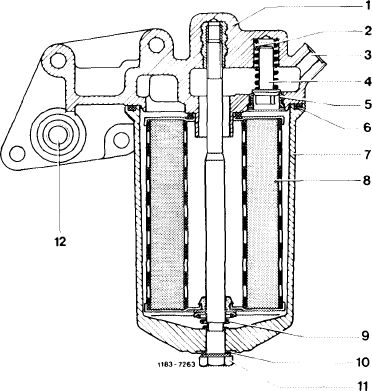
Oil filter models 114 and 116.020 USA and Sweden version
|
 |
|||
|
Model 280 (114.060) from chassis end No. 014 232 Model 280 C (114.073) from chassis end No. 003 385
Note: Oil filters up to and from the specified chassis end numbers are interchangeable.
|
||||
|
1 Filter upper section 8
2 Spring 9
3 Oil pressure gage connection
4 Filter cartridge bypass valve 10
5 Valve seat 11
6 Seal 12
7 Filter lower section
|
Filter cartridge
Spring with spring
retainer
Seal
Hex. head screw
17°C temperature
switch connection
|
|||
|
|
||||
|
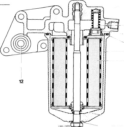
Oil filter without air oil cooler, model year 1977
|
1 2 3
4 5 6
7 8
|
|||
|
|
||||
|
1 Filter upper section
2 Spring
3 Oil pressure gage connection
4 Filter cartridge bypass valve
5 Valve seat
6 Seal
7 Filter lower section
8 Filter cartridge
9 Spring with spring retainer
10 Seal
11 Hex. head screw
12 17°C temperature switch connection
 |
9
10 11
|
|||
|
|
||||
|
18.2-005/5 F3
|
||||
|
|
||||
|
|
|||||||||||||||||||||||||||||||||||||||||||||||||||||||||||||||||
|
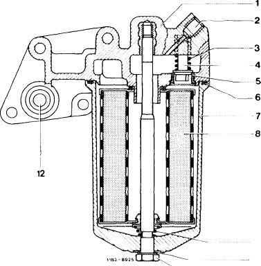
Oil filter model 126 without air oil cooler
|
|||||||||||||||||||||||||||||||||||||||||||||||||||||||||||||||||
|
|
|||||||||||||||||||||||||||||||||||||||||||||||||||||||||||||||||
|
9 10 11
 |
||||||||||||||||||||||||||||||||||||||||||||||||||||||||||||||||
|
|
|||||||||||||||||||||||||||||||||||||||||||||||||||||||||||||||||
|
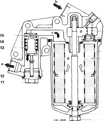
Oil filter model 126 with air oil cooler
|
 |
1 2
3 4
5 6
7
|
|||||||||||||||||||||||||||||||||||||||||||||||||||||||||||||||
|
1 Filter upper section 10
2 Connection for oil 11 pressure transmitter 12
3 Compression spring 13
4 Filter cartridge bypass valve 14
5 Sealing ring 15
6 Filter lower section
7 Filter cartridge a
8 Compression spring with b spring retainer c
9 Sealing ring d
|
Hex. head screw Closing plug Sealing ring Thermostat Control valve Compression spring
To air oil cooler From air oil cooler From oil pump To bearing points
|
||||||||||||||||||||||||||||||||||||||||||||||||||||||||||||||||
|
8
9
10
|
|||||||||||||||||||||||||||||||||||||||||||||||||||||||||||||||||
|
|
|||||||||||||||||||||||||||||||||||||||||||||||||||||||||||||||||
|
18.2-005/6 F3
|
|||||||||||||||||||||||||||||||||||||||||||||||||||||||||||||||||
|
|
|||||||||||||||||||||||||||||||||||||||||||||||||||||||||||||||||
|
|
||||
|
Note
|
||||
|
|
||||
|
Engines 110 are provided with oil filter elements of engines 116, 117 as standard equipment. The part no. of the filter element on oil filter bowl has been changed from the former 000 184 98 25 to 00 184 99 25.
The former filter element, part no. 000 184 98 25 is valid as a running-in filter up to 1st inspection.
Starting 1980, the oil filters, part no. 001 184 64 25 are valid as running-in filters or 001 184 65 25 as constant operation filters.
When the oil filter is removed, remainders of gasket may stick to flange surface of cylinder crankcase.
To prevent such remainders from entering the pure oil duct of the cylinder crankcase during removal (e.g. by scraping), the bores should be covered or closed first.
|
||||
|
|
||||
|
New oil filters are supplied with running-in filter elements which may be used on new engines up to first inspection.
These filter elements have a restricted operating life and should be exchanged against normal filter elements when new oil filters are installed on run-in engines.
|
||||
|
|
||||
|
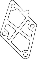
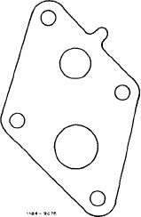
To prevent that the former gasket (A), part no. 110 184 03 80, is pushed out and thereby made leaking, the present version (B), part no. 110 184 05 80, is perforated only in range of forward or return flow.
|
 |
B
|
||
 |
||||
|
|
||||
|
18.2-005/7 F3
|
||||
|
|
||||
|
|
|||||||||||||||||||||||||||||||||||||||||
|
Standard application
|
|||||||||||||||||||||||||||||||||||||||||
|
|
|||||||||||||||||||||||||||||||||||||||||
|
Engine
|
starting engine end no. manual transmission
|
automatic transmission
|
|||||||||||||||||||||||||||||||||||||||
|
|
|||||||||||||||||||||||||||||||||||||||||
|
110.922 110.923 110.932 110.984 110.985 110.986
|
040354 013226 010320 019263 013841 003040
|
067119 017239 002765 065273 068010 006862
|
|||||||||||||||||||||||||||||||||||||||
|
|
|||||||||||||||||||||||||||||||||||||||||
|
|||||||||||||||||||||||||||||||||||||||||
|
|
|||||||||||||||||||||||||||||||||||||||||
|
’) On vehicles without air oil cooler deduct 0.5 liter refill capacity from total filling capacity.
|
|||||||||||||||||||||||||||||||||||||||||
|
|
|||||||||||||||||||||||||||||||||||||||||
|
Oil level checkup
|
|||||||||||||||||||||||||||||||||||||||||
|
|
|||||||||||||||||||||||||||||||||||||||||
|
The oil level depends, among others, from oil temperature and return flow period of oil after stopping the engine. For this reason, measure oil level only approx. 2 minutes after stopping worn engine.
Prior to checking oil level, always pull out dipstick first and wipe off.
|
|||||||||||||||||||||||||||||||||||||||||
|
|
|||||||||||||||||||||||||||||||||||||||||
|
Air oil cooler
|
|||||||||||||||||||||||||||||||||||||||||
|
|
|||||||||||||||||||||||||||||||||||||||||
|
Model 126.021 with engine 110.924 is not provided with an air oil cooler.
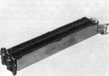
Models 126.022/023 are provided with a double tube light alloy air oil cooler.
|
 |
||||||||||||||||||||||||||||||||||||||||
|
|
|||||||||||||||||||||||||||||||||||||||||
|
Double tube light alloy air oil cooler
|
|||||||||||||||||||||||||||||||||||||||||
|
|
|||||||||||||||||||||||||||||||||||||||||
|
18.2-005/8 F3
|
|||||||||||||||||||||||||||||||||||||||||
|
|
|||||||||||||||||||||||||||||||||||||||||