Testing breakerless transistorized ignition
|
|
|||||||||||||||||||||||||||||||||||||||||||||||||||||
|
15—562 Testing breakerless transistorized ignition
|
|||||||||||||||||||||||||||||||||||||||||||||||||||||
|
|
|||||||||||||||||||||||||||||||||||||||||||||||||||||
|
A. TSZ 4
|
|||||||||||||||||||||||||||||||||||||||||||||||||||||
|
|
|||||||||||||||||||||||||||||||||||||||||||||||||||||
|
Conventional testers
|
|||||||||||||||||||||||||||||||||||||||||||||||||||||
|
|
|||||||||||||||||||||||||||||||||||||||||||||||||||||
|
|||||||||||||||||||||||||||||||||||||||||||||||||||||
|
|
|||||||||||||||||||||||||||||||||||||||||||||||||||||
|
Terminal 1 and ground
|
0.5-2.0 V
|
||||||||||||||||||||||||||||||||||||||||||||||||||||
|
|
|||||||||||||||||||||||||||||||||||||||||||||||||||||
|
Voltage ignition coil
|
|||||||||||||||||||||||||||||||||||||||||||||||||||||
|
|
|||||||||||||||||||||||||||||||||||||||||||||||||||||
|
Terminal 15 and ground
|
approx. 4.5 V
|
||||||||||||||||||||||||||||||||||||||||||||||||||||
|
|
|||||||||||||||||||||||||||||||||||||||||||||||||||||
|
Input voltage pre-resistor (series resistor)
|
approx. 12 V
|
||||||||||||||||||||||||||||||||||||||||||||||||||||
|
|
|||||||||||||||||||||||||||||||||||||||||||||||||||||
|
primary terminal 1 and 15
|
0.33-0.46
|
||||||||||||||||||||||||||||||||||||||||||||||||||||
|
|
|||||||||||||||||||||||||||||||||||||||||||||||||||||
|
secondary terminal 1 and 4
|
7-12
|
||||||||||||||||||||||||||||||||||||||||||||||||||||
|
|
|||||||||||||||||||||||||||||||||||||||||||||||||||||
|
Transmitter resistance between terminal 7 and 31 d
|
600+ 100
|
||||||||||||||||||||||||||||||||||||||||||||||||||||
|
|
|||||||||||||||||||||||||||||||||||||||||||||||||||||
|
Transmitter coil with control line terminal 7 and ground
|
|||||||||||||||||||||||||||||||||||||||||||||||||||||
|
|
|||||||||||||||||||||||||||||||||||||||||||||||||||||
|
approx. 1500 rpm
|
33-51
|
||||||||||||||||||||||||||||||||||||||||||||||||||||
|
|
|||||||||||||||||||||||||||||||||||||||||||||||||||||
|
Dwell angle at
|
|||||||||||||||||||||||||||||||||||||||||||||||||||||
|
|
|||||||||||||||||||||||||||||||||||||||||||||||||||||
|
approx. 5000 rpm
|
45-55
|
||||||||||||||||||||||||||||||||||||||||||||||||||||
|
|
|||||||||||||||||||||||||||||||||||||||||||||||||||||
|
) Perform dwell angle test at 5000 rpm only if complaints refer to misfiring at high speeds.
|
|||||||||||||||||||||||||||||||||||||||||||||||||||||
|
|
|||||||||||||||||||||||||||||||||||||||||||||||||||||
|
15.2 llb-562/1 F2
|
|||||||||||||||||||||||||||||||||||||||||||||||||||||
|
|
|||||||||||||||||||||||||||||||||||||||||||||||||||||
|
|
||||||
 |
||||||
|
|
||||||
|
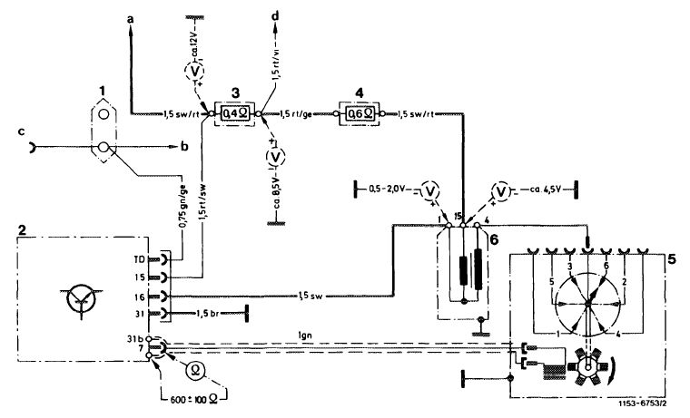
Wiring diagram breakerless transistorized ignition TSZ 4
|
||||||
|
|
||||||
|
1 Double cable connector
2 Switching unit
3 Pre-resistor 0.4 £1
4 Pre-resistor 0.6 £2
5 Ignition distributor with transmitter section
6 Ignition coil
|
a Ignition switch terminal 15
b Instrument cluster, revolution counter
c Diagnosis socket
d Terminal 16 starter
|
Color code br = brown ge = yellow
|
||||
|
gn
rt
|
= green
= red
|
|||||
|
sw = black
|
||||||
|
|
||||||
|
Note
|
 |
|||||
|
In the event of complaints about misfiring, test high voltage side of ignition system first (spark plugs, ignition cable, spark plug connectors).
If the complaints refer to firing of engine, complete the following tests on ignition system in addition to tests at fuel end:
|
||||||
|
|
||||||
|
Visual checkup
|
||||||
|
|
||||||
|
Check electrical screw connections and plug connections of ignition system for tight seat.
|
||||||
|
|
||||||
|
15.2 llb-562/2 F2
|
||||||
|
|
||||||
|
|
||||||
|
Voltage test
|
||||||
|
|
||||||
|
Note: With the ignition switched on and the engine stopped a primary current of approx. 8 amps will flow continuously through system.
1 Input voltage at series resistor 0.4 Cable color black/red:
Rated value approx. 12 volts
|
||||||
|
|
||||||
|
|
o.
|
|
||||
|
2 Voltage at ignition coil at approx. 20 C:
Terminal 15 and ground = approx. 4.5 volts Terminal 1 and ground = 0.5—2.0 volts
a) If value at terminal 1 is exceeded, the switching unit is defective and should be replaced.
b) If value at terminal 1 is attained, but no ignition voltage (ignition spark) is induced, check transmitter section in ignition distributor and secondary winding of ignition coil.
Resistance values of ignition coil:
Primary winding terminal 15 and terminal 1 = 0.33-0.46 n .
Secondary winding terminal 1 and terminal 4 = 7-12
|
||||||
|
|
||||||
|
Testing dwell angle
|
||||||
|
|
||||||
|
Note: The dwell angle cannot be adjusted. Testing is a functional inspection of switching unit (dwell angle control).
Connect dwell angle measuring unit (connection similar to SI standard switching unit).
Rated value at
Engine speed Dwell angle
1500±50/min 33-51°
|
||||||
|
|
||||||
|
|
||||||
|
|
o
|
|
||||
|
5000±50/min!) 45-55
) Test at 5000/min only in the event of complaints about misfiring at high speeds.
If this value is not attained when measuring dwell angle, check ignition distributor transmitter section first. If transmitter section is in order, replace switching unit.
|
||||||
|
|
||||||
|
15.2 llb-562/3 F2
|
||||||
|
|
||||||
|
|
|||||
|
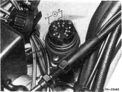
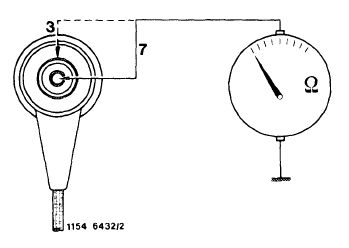
Testing ignition distributor transmitter section
|
|||||
|
|
|||||
|
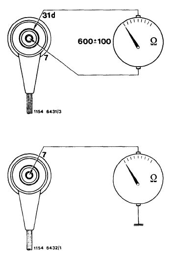
Pull control line of ignition distributor from switching unit and connect ohmmeter.
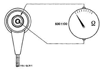
1 Check transmitter resistance between terminal 7 and 31 d.
Rated value: 600 ± 100ft
Note: On cold engine, the ohmic value should be in lower half of specified value, on warm engine in upper half.
|
 |
||||
|
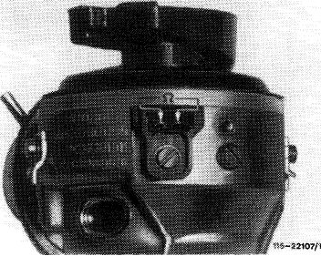
2 Test transmitter coil including control line for ground connection between terminal and ground.
Rated value: °°
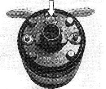
3 Check transmitter for mechanical damage. Check foi presence of air gap between rotor and stator.
Note: If the transmitter section is defective, replace complete ignition distributor.
|
|||||
|
|
|||||
|
B. TSZ 8 u
|
|||||
|
|
|||||
|
Conventional test instruments
|
|||||
|
|
|||||
|
Voltmeter, ohmmeter, dwell angle measuring instrument, revolution counter
|
|||||
|
|
|||||
|
Digital tester
|
e. g. made by Bosch, MOT 001.03
|
||||
|
|
|||||
|
Test values Resistors
|
|||||
|
|
|||||
|
primary (terminal 1 and 15)
|
approx. 0.5—0.9 ft
|
||||
|
|
|||||
|
Ignition coil
|
|||||
|
|
|||||
|
secondary (terminal 1 and 4)
|
6-16kft
|
||||
|
|
|||||
|
Distributor cap
|
1 kft
|
||||
|
|
|||||
|
Distributor rotor, spark plug connector
|
1 kft
|
||||
|
|
|||||
|
Resistance of winding Ignition distributor transmitter section—————————–
|
600± 100ft
|
||||
|
|
|||||
|
Resistance against ground
|
> 200 kft
|
||||
|
|
|||||
|
15.2 llb-562/4 F2
|
|||||
|
|
|||||
|
|
|||||
|
Voltages, stopped engine, ignition switched on
|
|||||
|
|
|||||
|
Terminal 15 (jack 5 diagnosis socket)
|
Battery voltage
|
||||
|
|
|||||
|
between terminal 15 and 1 (jack 5 and 4 diagnosis socket)
|
OVolt
|
||||
|
|
|||||
|
Dwetl angle
|
|||||
|
|
|||||
|
Terminal TD at starting speed
|
from 7 ° to 25
|
||||
|
|
|||||
 |
|||||
|
|
|||||
|
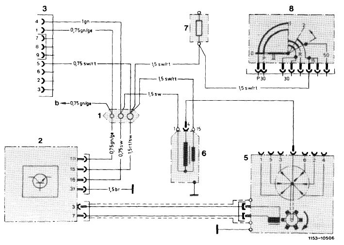
Wiring diagram breakerless transistorized ignition without pre-resistors TS2 8 u
|
|||||
|
|
|||||
|
1 Line connector
2 Switching unit
3 Diagnosis socket
5 Ignition distributor
6 Ignition coil
7 Fuse box terminal 15
8 Ignition starter switch
|
b To fuel pump relay with rpm limitation
|
Color code br = brown ge = yellow gn = green rt = red sw = black
|
|||
|
|
|||||
|
15.2 lib—562/5 F2
|
|||||
|
|
|||||
|
|
||||
|
Test
|
 |
|||
|
Test voltage (terminal 15) against ground at jack 5 of diagnosis socket. Ignition switched on.
Nominal value: battery voltage
|
||||
|
Nominal value correct.
|
Nominal value wrong.
|
|||
|
|
||||
 |
||||
|
|
||||
|
Test voltage supply via ignition lock.
|
||||
|
|
||||
|
Test voltage difference between jack 5 and 4 (terminal 15 and 1) of diagnosis socket.
Nominal value: Ovolt
|
||||
|
|
||||
|
Nominal value correct.
|
Nominal value wrong (voltage >0.1 volt).
Switch off ignition immediately.
|
|||
|
|
||||
 |
||||
|
|
||||
|
Replace switching unit.
|
||||
|
|
||||
 |
||||
|
|
||||
|
15.2 llb-562/6 F2
|
||||
|
|
||||
|
|
||||||
|
Test plug in ignition coil and primary resistance of ignition coil (between terminal 1 and 15) 0.5-0.9 SI.
With plug ejected or wrong ohmic value, replace ignition coil.
End of test.
|
 |
U5-3:1388
|
||||
|
|
||||||
 |
||||||
|
|
||||||
|
Test dwell angle at starting speed at diagnosis socket or terminal TD.
Nominal value: from 7—25°.
|
||||||
|
|
||||||
|
Nominal value correct.
|
Nominal value not indicated.
|
Nominal value higher than 34C
|
||||
|
|
||||||
 |
||||||
|
|
||||||
|
Replace switching unit.
|
||||||
|
|
||||||
|
End of test
|
||||||
|
|
||||||
|
Test ignition distributor transmitter section for interruption and interturn short.
Pull off green control line on switching unit. Test resistance with ohmmeter between terminal 7 and 3.
Nominal value: 600 ± 100 £2
|
 |
|||||
|
Nominal value correct.
|
Nominal value wrong.
|
|||||
 |
||||||
|
|
||||||
|
15.2 llb-562/7 F2
|
||||||
|
|
||||||
|
|
|||||
|
Pull off plug connection of green cable on ignition distributor and test with ohm-meter at plugs whether 600 ± 100 O is indicated.
If nominal value is attained, replace green cable.
If nominal value is not attained, replace ignition distributor.
|
 |
||||
|
|
|||||
 |
 |
||||
|
|
|||||
|
Test ignition distributor transmitter section for ground connection.
Pull off green cable on switching unit. Connect ohmmeter to terminal 3 or 7 and to ground.
Nominal value: > 200 kfi
|
 |
||||
|
Nominal value correct.
|
Nominal value wrong.
|
||||
|
|
|||||
 |
 |
||||
|
End of test
|
Pull off plug connection of green cable on ignition distributor. Test resistance against ground.
Nominal value at both plugs: = 200 ktu
If nominal value is not attained at one plug, replace ignition distributor.
|
||||
|
|
|||||
|
15.2 Mb—562/8 F2
|
|||||
|
|
|||||