General description of breaker-controlled transistorized ignition
|
|
|||
|
07.5—519 General description of breaker-controlled transistorized ignition
|
|||
|
|
|||
|
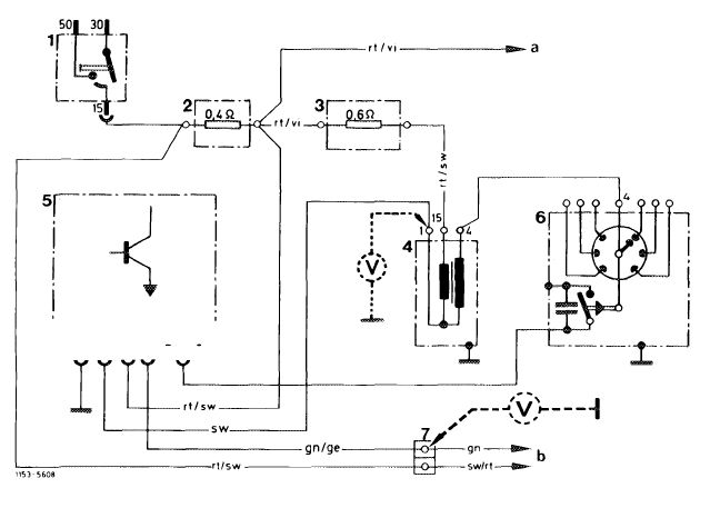
Layout of transistorized ignition
|
 |
||
|
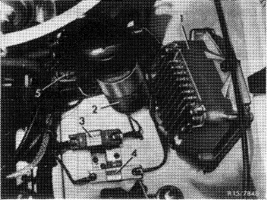
The system comprises:
Switchgear Ignition coil Pre-resistor 0.4 ohm (3) Pre-resistor 0.6 ohm (4)
|
|||
|
Operation
|
|||
|
The ignition coil current is controlled by a transistorized circuit instead of the breaker point. The transistorized circuit is controlled by the breaker point.
With the breaker point closed, the switching transistor is conductive. When the breaker point opens, the transistor locks and the ignition coil current is interrupted. As a result of the interrupted circuit in the primary winding, the ignition voltage is induced in the secondary winding as before for conventional coil ignition.
To increase the ignition voltage, the 0.4 ohm pre-resistor is bridged by contact 16 on starter while starting.
|
|||
|
|
|||
|
Switchgear (1)
The switchgear has several transistors, resistors and other electronic components in a metal housing. This housing protects the components against mechanical damage and splash water and also serves to dissipate the heat due to energy losses. Contact on switchgear is made by a 4-way round plug connection with separate coaxial connection for activation.
In the event of repairs, only the complete switch-gear can be exchanged.
|
|||
|
|
|||
|
07.5.2 Ib—519/1
|
|||
|
|
|||
|
|
||
|
Ignition coil (2)
|
||
|
|
||
|
Layout and external dimensions of ignition coil correspond to those of a normal heavy-duty ignition coil. But the design of the winding is different. The ratio amounts to approx. 1:185 as compared with 1:100 for conventional ignition coils.
External identification: painted blue.
|
||
|
|
||
|
Pre-resistors
|
||
|
|
||
|
Resistors 0.4 ohm and 0.6 ohm are designed similar to the ignition coil pre-resistors installed up to now: A ceramic body encloses the resistor winding, with extending connections.
A sheet metal clamp is placed around ceramic body for attachment. The color of this clamp informs about the resistance value, which is additionally punched in as a number.
|
||
|
|
||
|
Color Code number Resistor
blue, anodised 0.4 0.4 ohm
metallic, anodised 0.6 0.6 ohm
|
||
|
|
||
|
General information
|
||
|
|
||
|
On vehicles with transistorized systems, do not operate engine without battery connected.
When using rapid charging units for charging vehicle battery, separate battery from other vehicle circuits.
Starting assistance with rapid chargers is not permitted.
When installing battery, pay attention to correct polarity.
Do not confuse line connections on switchgear (e.g. when testing switchgear in installed condition).
Switchgear may suffer damage if these instructions are not observed.
|
||
|
|
||
|
07.5.2 lb-519/2
|
||
|
|
||
|
|
|||||||||||||||||||||||||||||||||||||||||||||||||||||||||||||||||||||||
|
Instructions concerning test jobs
|
|||||||||||||||||||||||||||||||||||||||||||||||||||||||||||||||||||||||
|
|
|||||||||||||||||||||||||||||||||||||||||||||||||||||||||||||||||||||||
|
On engines with transistorized coil ignition, speed and dwell angle cannot always be measured in the usual manner.
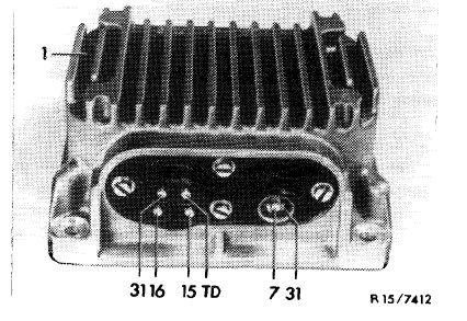
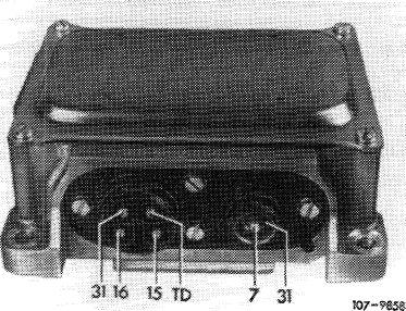
Depending on type of tester used, connection at different points of ignition system is required. Always refer to operating instructions for tester. To facilitate connection of speed and dwell angle testers, an empty, offset cable shoe is screwed underneath cable connector 7.
|
|||||||||||||||||||||||||||||||||||||||||||||||||||||||||||||||||||||||
|
|
|||||||||||||||||||||||||||||||||||||||||||||||||||||||||||||||||||||||
|
|||||||||||||||||||||||||||||||||||||||||||||||||||||||||||||||||||||||
|
|
|||||||||||||||||||||||||||||||||||||||||||||||||||||||||||||||||||||||
|
L 31 !LJ5 TD 7 J
TFTTT
|
||||||||||||||||||||||||||||||||||||||||||||||||||||||||||||||||||||||
|
|
|||||||||||||||||||||||||||||||||||||||||||||||||||||||||||||||||||||||
|
07.5.2 lb-519/3
|
|||||||||||||||||||||||||||||||||||||||||||||||||||||||||||||||||||||||
|
|
|||||||||||||||||||||||||||||||||||||||||||||||||||||||||||||||||||||||
|
|
|||
|
Switchgear 0 227 051 014
|
 |
||
|
|
|||
|
Switchgear 0 227 051 024
|
 |
||
|
|
|||
|
07.5.2 lb-519/4
|
|||
|
|
|||