Testing breaker-controlled transistorized ignition (T) (us*
|
|
||
|
07.5—520 Testing breaker-controlled transistorized ignition (T) (us*
|
||
|
|
||
|
Conventional tools
|
||
|
|
||
|
1 voltmeter, measuring range 0—3 V, 0—15 V with 0.1 V scale graduation
|
||
|
|
||
|
1 ohmmeter, measuring range starting 0.1 ohm
|
||
|
|
||
|
1. Testing pre-resistors
|
||
|
|
||
|
Loosen line connection on one connection of resistor about to be tested.
Measure resistance with ohmmeter.
Pre-resistor Resistor rated value at 20 °C
0.4 ohm 0.4 ± 0.05 ohm
0.6 ohm 0.6 ± 0.05 ohm
Values on warmer pre-resistors will be slightly higher.
|
||
|
|
||
|
2. Testing ignition coil
|
||
|
|
||
|
Insulation test
Separate ignition coil from vehicle circuits by removing terminals 1,15 and 4.
Connect engine tester to ignition coil. Perform test according to operating instructions.
Whenever possible, test ignition coil with a suitable engine tester (e.g. SUN 745 or 1130) under operating conditions. This will show above all insulation damage, ground and winding shorts.
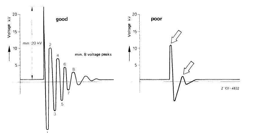
Evaluate voltage flow on scope according to the following illustration.
|
||
|
|
||
|
07.5.2 lb-520/1
|
||
|
|
||
|
|
|||
 |
|||
|
|
|||
|
Selection Line-up
Fault Voltage below 20 kv, less than 8 voltage peaks
Cause Interrupted winding, winding short or insulation damage against ground
Remedy Renew ignition coil
|
|||
|
|
|||
|
Evaluation
The ignition coil is perfect, if the first oscillation attains 20 kv, followed by min. 8 voltage peaks. If this value is not attained, replace ignition coil.
|
|||
|
|
|||
|
Resistance test
|
|||
|
|
|||
|
Resistance rated value at 20 °C
|
|||
|
|
|||
|
Primary winding measured between terminal 1 and terminal 2
|
0.38-0.45 ohm
|
||
|
|
|||
|
Secondary winding measured between terminal 1 and terminal 4
|
8-11 kohm
|
||
|
|
|||
|
Measuring values are slightly higher when ignition coil is warm.
|
|||
|
|
|||
|
07.5.2 lb-520/2
|
|||
|
|
|||
|
|
|||
|
3. Testing breaker point
|
|||
|
|
|||
|
For perfect functioning of transistorized systems the transfer resistance on breaker point should not be too high. To check, measure voltage drop at closed breaker point.
Connect voltmeter: + to cable connector
(= terminal 7 or TD on switchgear) — to ground
Voltage readout max. 0.3 volt.
If this value is exceeded, install a new breaker point.
|
|||
|
|
|||
|
4. Testing switchgears and line connections
Test for voltage on switchgear and whether the switching transistor permits passage of ignition coil primary current or locks at pertinent activation. The primary current will not be measured directly, but the voltage drop caused by this current for the sake of simplicity.
The test is made with the engine stopped and the ignition switched on.
Test voltage drop at input of 0.4 ohm resistor with breaker point closed.
Connect voltmeter: + to input pre-resistor 0.4 ohm
— to ground
The voltage drop may amount to max. 0.4 volt.
If voltage drop is too high, test cable and cable connections.
|
|||
|
|
|||
|
4.1 Standard switchgears (SI) Checking line connections
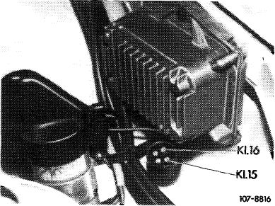
Pull 4-pole connecting plug from switchgear and test with voltmeter whether a battery voltage of 11.8-13 volts is available at terminal 15 and terminal 16 on 4-point plug with the ignition switched on.
|
 |
||
|
|
|||
|
07.5.2 lb-520/3
|
|||
|
|
|||
|
|
|||
|
Connect voltmeter: + to terminaM5 or
terminal 16 — to ground
If no voltage is measured, check all connections from input 0.4 ohm resistor to switchgear.
Then reattach 4-point round plug to switchgear.
|
|||
|
|
|||
|
Voltage with breaker point open
This will test tripping characteristics of transistor.
Connect voltmeter: + to terminaM ignition coil
— to ground
Battery voltage should be available at terminal 1, i.e. readout = 11.8-13 volts.
If not, replace switchgear.
|
|||
|
|
|||
|
Voltage with breaker contact closed
Voltmeter connected as before.
Voltage at terminal 1 ignition coil = 0.7—1.5 volts.
With breaker point closed, terminal 15 of ignition coil will show 3.6—4.6 volts, with open breaker point battery voltage.
If not, replace switchgear.
|
|||
|
|
|||
|
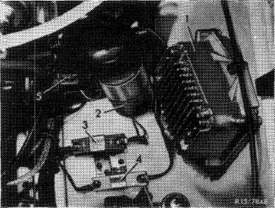
Layout of transistorized system with switchgear in model 114.060/073
1 Standard switchgear
2 Ignition coil
3 Pre-resistor 0.4 ohm
4 Pre-resistor 0.6 ohm
5 Cable shoe for test connection (cable color green/yellow)
|
 |
||
|
|
|||
|
07.5.2 lb-520/4
|
|||
|
|
|||
|
|
||||||||||||||||||||||||||||||||||||||||||||||||||||||||||||||
|
Test values for switchgear test
|
||||||||||||||||||||||||||||||||||||||||||||||||||||||||||||||
|
|
||||||||||||||||||||||||||||||||||||||||||||||||||||||||||||||
|
Measuring points of associated voltage values for transistorized systems
|
||||||||||||||||||||||||||||||||||||||||||||||||||||||||||||||
|
|
||||||||||||||||||||||||||||||||||||||||||||||||||||||||||||||
|
||||||||||||||||||||||||||||||||||||||||||||||||||||||||||||||
|
|
||||||||||||||||||||||||||||||||||||||||||||||||||||||||||||||
|
07.5.2 lb-520/5
|
||||||||||||||||||||||||||||||||||||||||||||||||||||||||||||||
|
|
||||||||||||||||||||||||||||||||||||||||||||||||||||||||||||||