Functional description positive and negative venting of fuel tank
|
|
||||
|
47—720 Functional description positive and negative venting of fuel tank
|
||||
|
|
||||
|
On model 107.04 and 123.09 an expansion tank is located outside fuel tank.
Model 107.02 is provided with an expansion tank which is installed in fuel tank and can therefore not be removed.
|
||||
|
|
||||
|
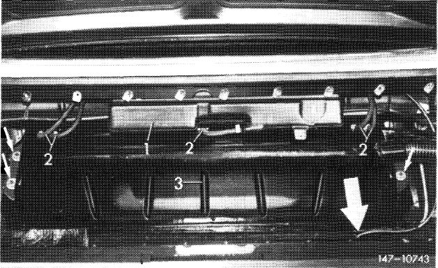
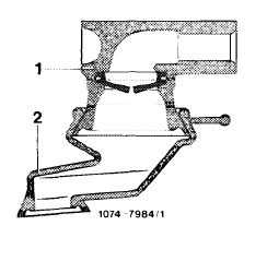
Model 107.04
1 Expansion tank
2 Fuel hoses
3 Fuel tank Large arrow = Vent line
|
 |
|||
|
|
||||
|
The fuel vapors escape from fuel tank into expansion tank and from there through vent line into atmosphere.
|
 |
|||
|
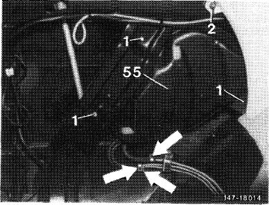
Model 123.09
55 Expansion tank
Arrows = Connecting lines to fuel tank
and vent line
|
||||
|
|
||||
|
47.2 lib—720/1 F 2
|
||||
|
|
||||
|
|
||||
|
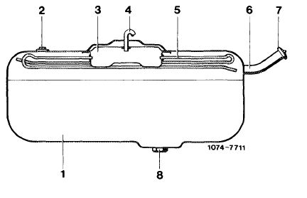
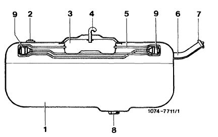
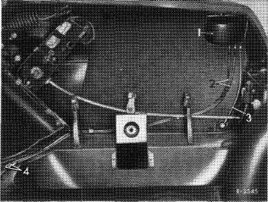
Models 116, 123 and 126 are provided with a vent system comprising a collecting tray and a pipe system.
|
||||
|
|
||||
|
3 Collecting tray
4 Vent line
5 Pipe system
|
 |
|||
|
|
||||
|
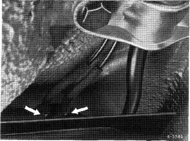
Since April 1980 additional check vessels are attached to ends of pipe system of model 126.
The following national version vehicles are also provided with check vessels:
^-v 1979 entering production model 123
|
 |
|||
|
1980 model 116
|
||||
|
1980/81, model 123
|
9 Check vessels
|
|||
|
|
||||
|
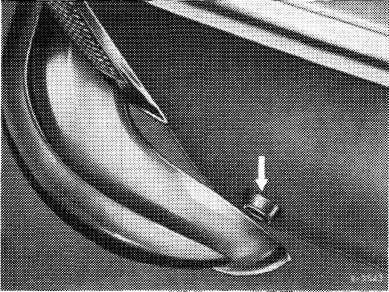
The fuel vapors escape through vent system to vent line and from there into atmosphere.
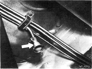
A protective sleeve (arrow) is plugged on at end of vent line on models 107.04, 126 and on all vehicles manufactured up to February 1979.
|
 |
|||
|
Model 126
Arrow = Protective sleeve
|
||||
|
|
||||
|
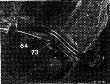
Starting March 1979 all vehicles (except model 107.04 and 126) are provided with a vent sleeve at end of vent line.
|
 |
|||
|
64 Vent line 73 Vent sleeve
|
||||
|
|
||||
|
47.2 llb-720/2 F2
|
||||
|
|
||||
|
|
|||
|
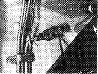
When repairing older vehicles, also install only vent sleeve with diaphragm. In such a case, the vent line must be rebent with a suitable mandrel in such a manner that the vent sleeve is pointing downwards.
Attention!
Avoid kinks in vent line when rebending.
|
 |
||
|
|
|||
|
Vent sleeve with diaphragm
|
 |
||
|
|
|||
|
47.2 llb-720/3 F2
|
|||
|
|
|||
|
|
|||
|
47—720 Functional description of fuel tank positive and negative venting system (model 114)
|
|||
|
|
|||
|
>up to January 1973 )up to end of series
|
|||
|
|
|||
|
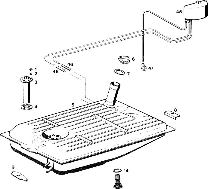
An expansion tank (1) in trunk serves for positive and negative venting of fuel tank.
|
 |
||
|
1 Expansion tank
2 Positive venting line to fuel tank
3 Negative venting line to atmosphere
4 Connecting hoses
|
|||
|
|
|||
|
The expansion tank is connected to two positive venting lines (arrows) entering the fuel tank and with one negative venting line (3) to atmosphere.
|
 |
||
|
Arrows = positive venting lines on fuel tank
|
|||
|
|
|||
|
If with the fuel tank filled, fuel is forced into positive venting line (2), the fuel can rise up to expansion tank. As soon as one of the two positive venting lines is free of fuel, the fuel will immediately flow back into fuel tank, while the fuel vapors escape into the open air through negative venting line (3).
The fuel vapors escape into the atmosphere at point shown in illustration (arrow).
|
 |
||
|
Arrow = outlet of fuel vapors into the atmosphere
|
|||
|
|
|||
|
47.2 Ib—720/1
|
|||
|
|
|||
|
|
||||||||||||||||||||||||||||||||||||||||||||||||||||||||
|
Model 114 Fuel system, fuel tank positive and negative venting
|
||||||||||||||||||||||||||||||||||||||||||||||||||||||||
|
|
||||||||||||||||||||||||||||||||||||||||||||||||||||||||
|
1472-7652
15
|
||||||||||||||||||||||||||||||||||||||||||||||||||||||||
|
©10
|
||||||||||||||||||||||||||||||||||||||||||||||||||||||||
|
|
||||||||||||||||||||||||||||||||||||||||||||||||||||||||
|
||||||||||||||||||||||||||||||||||||||||||||||||||||||||
|
|
||||||||||||||||||||||||||||||||||||||||||||||||||||||||
|
47.2 lb-720/2
|
||||||||||||||||||||||||||||||||||||||||||||||||||||||||
|
|
||||||||||||||||||||||||||||||||||||||||||||||||||||||||