Fuel evaporation control system
|
|
||||
|
47—800 Fuel evaporation control system
|
||||
|
|
||||
 |
||||
|
|
||||
|
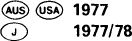
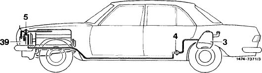
The fuel evaporation control system which prevents the escape of evaporation vapors from fuel system into the atmosphere comprises the following components:
|
||||
|
|
||||
|
2 Valve system
3 Fuel tank
39 Charcoal canister
|
 |
|||
|
|
||||
|
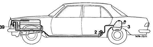
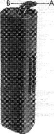
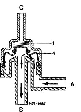
Valve system
The valve system is mounted underneath vehicle at level of rear legroom.
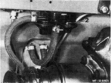
The valve system comprises three valves:
1. Pressure relief valve (negative vent valve)
2. Safety valve
3. Vacuum relief valve (positive vent valve)
The pressure relief valve opens at a slight overpressure. The evaporation vapors will flow through pressure relief valve (1) (direction B) in a line toward charcoal canister.
|
 |
|||
|
|
||||
|
The safety valve opens in the event of overpressure in fuel evaporation control system. The fuel vapors will be vented directly into the atmosphere.
The vacuum relief valve opens in the event of a vacuum established when the fuel tank is cooling down.
 |
||||
|
|
||||
|
1 Pressure relief valve
2 Safety valve
3 Vacuum relief valve
A To valve/to expansion tank
B To charcoal canister
C Fresh air inlet
D Outlet safety valve
|
||||
|
|
||||
|
47.2 lib—800/1 F 2
|
||||
|
|
||||
|
|
||||
|
Charcoal canister
The fuel evaporation vapors from fuel tank are stored in charcoal canister and drawn off again while driving.
|
 |
107-9128
|
||
|
A Connection, fuel vapors from tank B Connection, throttle valve housing
|
||||
|
|
||||
|
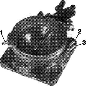
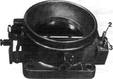
Throttle valve housing
The throttle valve housing is provided with a connection for drawing evaporation vapors from charcoal canister.
|
 |
107-13053
|
||
|
1 Vacuum connection ignition retard
2 Vacuum connection ignition advance
3 Vacuum connection charcoal canister
|
||||
|
|
||||
|
The fuel tank with fuel expansion tank and the valve system correspond to the already known version.
|
||||
|
|
||||
|
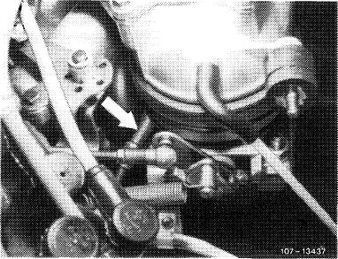
Description of operation
|
 |
|||
|
The fuel vapors from fuel tank are routed to charcoal canister via valve system (2). The fuel evaporation vapors are stored in charcoal canister when the engine is stopped and are drawn off into throttle valve housing when the engine is running as from a given throttle valve position.
For checkup refer to: Exhaust gas test program
|
||||
|
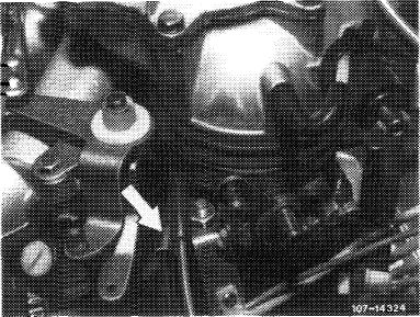
Arrow = Draw-off line to throttle valve housing
|
||||
|
|
||||
|
47.2 llb-800/2 F2
|
||||
|
|
||||
|
|
||||
|
(aus)(usa) 1978-1980 CD 1979/80
|
||||
|
|
||||
|
The fuel evaporation control system has been completely revised to meet the new limits specified by law.
 |
||||
|
|
||||
|
3 Fuel tank
4 Vent valve unit
5 Purge valve
39 Charcoal canister
|
||||
|
|
||||
|
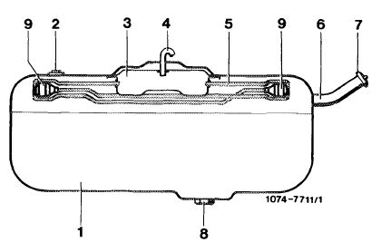
The system comprises the following components: Fuel tank
The fuel tank with the tube system and the collecting tray are identical to the already known versions.
|
 |
|||
|
1 Fuel tank
2 Immersion tube transmitter
3 Expansion tank
4 Connection vent valve unit
5 Tube system
6 Filler neck
7 Closing cover
|
8 Connection fuel feed line
9 Check vessels entering production starting 1979 (T) (model 123)
starting 1980 (model 123) model 126 starting 1981
 |
|||
|
|
||||
|
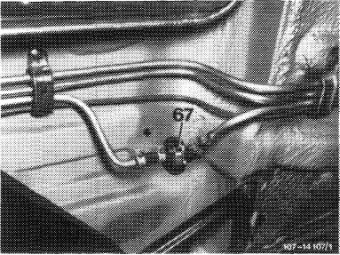
Vent valve unit
|
 |
|||
|
The vent valve unit (67) is mounted underneath vehicle at level or rear legroom and replaces the valve system known from model year 1977.
The unit comprises a pressure relief valve (negative vent valve) and a vacuum relief valve (positive vent valve).
|
||||
|
|
||||
|
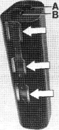
Charcoal canister
The charcoal canister is identical with the already known version, except that the fastening bracket (arrows) has been modified.
|
 |
|||
|
A Draw-off line to throttle valve housing B Fuel tank vent line
|
||||
|
|
||||
|
47.2 llb-800/3 F 2
|
||||
|
|
||||
|
|
|||
|
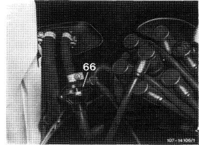
Purge valve
The purge valve (66) is located in purge line from charcoal canister to throttle valve housing.
|
 |
||
|
|
|||
|
Throttle valve housing
In comparison to model year 1977 the throttle valve housing has been slightly modified. To prevent a mix-up of the vacuum lines, the outside diameter of the vacuum line to the charcoal canister has been increased from 4 to 5 mm. To purge the fuel vapors from the charcoal canister, two purge bores are provided above the throttle valve.
|
 |
||
|
|
|||
|
2 Vacuum connection, ignition advance
3 Vacuum connection, charcoal canister
|
|||
|
|
|||
|
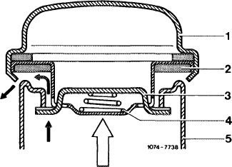
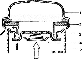
Fuel tank cap
To avoid excessive pressure in fuel tank, the fuel tank cap has been modified.
|
 |
||
|
1 Fuel tank cap
2 Gasket
3 Locking tab
4 Compression spring
5 Filler neck
|
|||
|
|
|||
|
Description of operation
|
|||
|
|
|||
|
Evaporation system
The pressure in fuel tank is increased to 30—50 mbar by means of the vent valve (67). This ensures that less fuel vapors can escape from tank.
|
|||
|
|
|||
|
47.2 llb-800/4 F2
|
|||
|
|
|||
|
|
|||
|
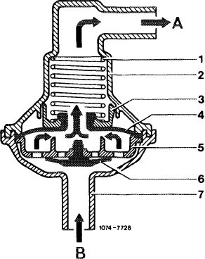
If a pressure of 30—50 mbar is reached in the fuel tank, the pressure relief valve (4) opens and permits the fuel vapors to travel to the charcoal canister, where they are stored if the engine is not running.
|
 |
||
|
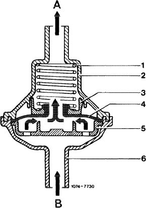
Vent valve unit, open to charcoal canister
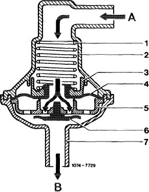
1 Compression spring
2 Valve housing
3 Spring seat
4 Pressure relief valve
5 Valve disk
6 Vacuum relief valve
7 Connection fitting
A Connection, charcoal canister B Connection, fuel tank
|
|||
|
|
|||
|
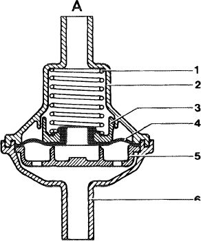
When the fuel cools down, the decreasing volume is balanced by the intake of air or of fuel evaporation vapors from charcoal canister via vacuum relief valve (6) starting at a vacuum of 1 — 16 mbar. If the vacuum in the fuel tank drops below 1 mbar, the vacuum relief valve (6) closes.
|
 |
||
|
Vent valve unit, open to fuel tank
|
|||
|
|
|||
|
If the pressure in the fuel tank increases above 100—300 mbar due to a malfunction in the fuel evaporation system, the fuel vapors can escape via the fuel filler cap.
|
 |
||
|
1 Fuel tank cap
2 Sealing ring
3 Locking tab
4 Compression spring
5 Filler neck
|
|||
|
|
|||
|
47.2 llb-800/5 F2
|
|||
|
|
|||
|
|
|||
|
Purge system
|
|||
|
|
|||
|
The charcoal canister is connected with the throttle valve housing by a hose in which the purge valve is installed.
When the engine is running and the vacuum in the purge line exceeds 30-50 mbar, the purge valve opens. The fuel vapors stored in the charcoal canister can be drawn into the throttle valve housing depending on the throttle valve position.
|
 |
||
|
Purge valve open
1 Compression spring
2 Valve housing
3 Spring seat
4 Pressure relief valve
5 Valve disk
6 Connection fitting
A Connection, throttle valve housing
B Connection, charcoal canister
|
|||
|
|
|||
|
As the throttle valve is opened, the two purge bores in the throttle valve housing, which terminate in a common passage, are progressively exposed to the venturi vacuum. This will result in a metered purging in the lower partial load operating range of the engine without influencing the driving characteristics.
|
 |
||
|
Arrow = Draw-off connection of throttle valve
|
|||
|
|
|||
|
At idle and during coasting (throttle valve closed) both purge bores are located on the atmosphere side of the throttle valve. The purge valve is closed and, therefore, no purging of fuel vapors from the charcoal canister takes place.
|
1074-7731
|
||
|
|
|||
|
Purge valve, closed
|
|||
|
|
|||
|
47.2 llb-800/6 F2
|
|||
|
|
|||
|
|
||||
|
starting 1981, (usa) 1981
|
||||
|
|
||||
|
The fuel evaporation control system has been revised in comparison to model year 1980. The purge system is controlled by means of a thermovalve and is effective only above approx. 50°C/122°F coolant temperature.
|
||||
|
|
||||
|
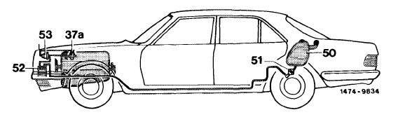
Functional diagram
|
||||
|
|
||||
|
37a Thermovalve 50 C/122 F
50 Fuel tank
51 Vent valve unit
52 Charcoal canister
53 Purge valve
|
||||
|
|
||||
|
Components of fuel evaporation control system
Only the new components are shown here.
 |
||||
|
|
||||
|
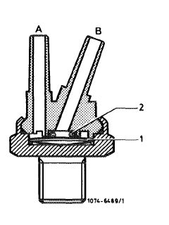
Thermovalve 50 °C/122 °F (37a, color code red)
The thermovalve is installed in the sensor box on the cylinder head and opens at an engine cooling temperature of 50 °C/122 °F.
|
 |
|||
|
1 Bimetallic plate A
2 O-ring B
|
To purge valve
To throttle valve housing
|
|||
|
|
||||
|
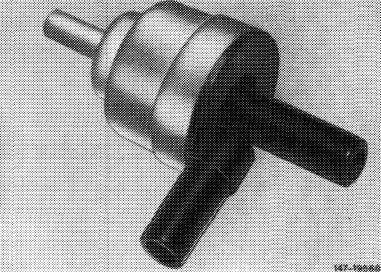
Purge valve (53, vacuum-controlled)
The purge valve is installed in the purge line from the charcoal canister to the throttle valve housing. It can be recognized by the vacuum connection to thermovalve 50 °C.
|
 |
|||
|
|
||||
|
47.2 llb-800/7 F 2
|
||||
|
|
||||
|
|
|||
|
Description of operation
|
 |
||
|
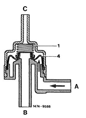
Purge system
The charcoal canister is connected to the throttle valve housing by a line in which the purge valve is installed.
|
|||
|
Purge valve closed
A Connection,charcoal canister
B Connection, throttle valve housing
C Vacuum connection
1 Compression spring
4 Diaphragm
|
|||
|
|
|||
|
When the engine is running at a coolant temperature above approx. 50 °C/122 °F, intake manifold vacuum is applied to the purge valve through the thermovalve with the throttle valve slightly raised. The diaphragm (4) is pulled in upward direction against the spring force and connection from A to B is made.
|
|||
|
|
|||
|
When the throttle valve is opened still further, the two purge openings, which terminate in a common passage, are progressively exposed to the venturi vacuum. This will result in a metered purging in the lower partial load operating range of the engine without influencing the driving characteristics.
|
 |
||
|
Purge valve, open
|
|||
|
|
|||
|
47.2 llb-800/8 F2
|
|||
|
|
|||
|
|
|||||||||||||||||||||||||||||||||||||||||||||||||||||||||||
|
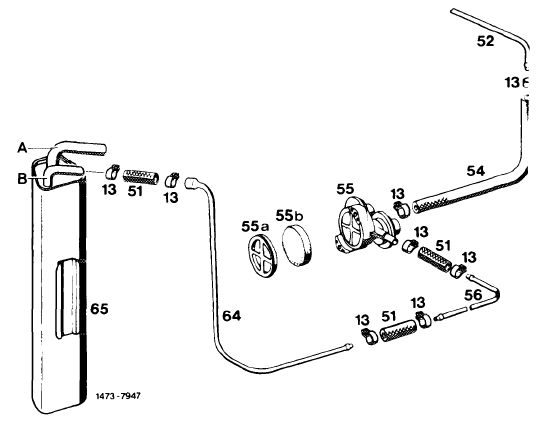
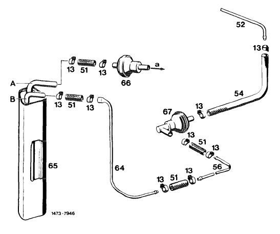
Fuel evaporation control system
|
|||||||||||||||||||||||||||||||||||||||||||||||||||||||||||
|
|
|||||||||||||||||||||||||||||||||||||||||||||||||||||||||||
|
(aus) (us^) 1977 CD 1977/78
|
 |
||||||||||||||||||||||||||||||||||||||||||||||||||||||||||
|
13 Hose clamp
51 Fuel hose
52 Vent line from fuel tank
54 Fuel hose
55 Valve system 55a Cover
55b Filter
56 Vent line
64 Vent line
65 Charcoal canister
A Draw-off line to throttle valve housing
B Fuel tank vent line
|
|||||||||||||||||||||||||||||||||||||||||||||||||||||||||||
|
|
|||||||||||||||||||||||||||||||||||||||||||||||||||||||||||
 |
1978-1980 1979/80
|
 |
|||||||||||||||||||||||||||||||||||||||||||||||||||||||||
|
|||||||||||||||||||||||||||||||||||||||||||||||||||||||||||
|
|
|||||||||||||||||||||||||||||||||||||||||||||||||||||||||||
|
47.2llb-800/9 F2
|
|||||||||||||||||||||||||||||||||||||||||||||||||||||||||||
|
|
|||||||||||||||||||||||||||||||||||||||||||||||||||||||||||
|
|
||||
 |
||||
|
|
||||
 |
||||
|
|
||||
|
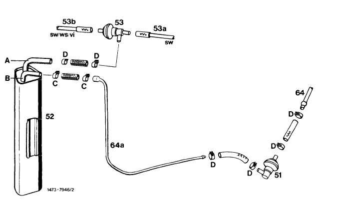
51 Vent valve
52 Charcoal canister
53 Purge valve
53a Draw-off line to throttle valve
53b Vacuum line
64 Vent line from fuel tank
64a Vent line to charcoal canister
|
A To purge valve
B To fuel tank
C Hose clamp
D Clamp
|
Color code sw = black vi = purple ws = white
|
||
|
|
||||
|
47.2 llb-800/10 F2
|
||||
|
|
||||