Fuel evaporation system
|
|
|||
|
47—800 Fuel evaporation system
|
|||
|
|
|||
|
Note
|
|||
|
|
|||
|
(T) starting January 1973 up to production model
year 1976 (@)1973, 1974 Federal
High outside temperatures and self-heating of returning fuel will also heat fuel tank. Legislation in a number of countries does not permit these fuel evaporation vapors to escape into the atmosphere.
For this reason, the fuels are drawn from fuel tank via crankcase breather into the combustion chambers when the engine is running, and they are stored in crankcase when the engine is stopped.
|
|||
|
|
|||
|
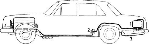
Model 114
From fuel tank, two lines are leading to expansion tank (capacity 4.5 I). The expansion tank is mounted at the right in trunk.
Both lines serve as venting, overflow or discharge lines depending on position of fuel level in fuel tank, on fuel volume and on temperature.
At the highest point of the expansion tank is the connection for the positive and negative venting line to valve system (2).
|
|||
|
|
|||
|
The fuel evaporation control system comprises:
|
|||
|
|
|||
|
Fuel expansion tank (1)
Valve system (2)
Fuel tank (3)
Draw-off connection on crankcase (4)
|
 |
||
|
|
|||
|
47.2 lb-800/1
|
|||
|
|
|||
|
|
||||
|
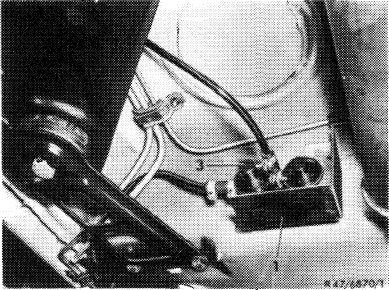
Valve system
|
 |
|||
|
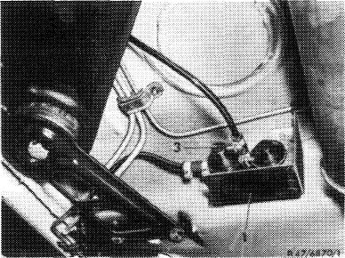
The valve system is mounted underneath vehicle at level of rear legroom.
The valve system comprises three valves:
1. Negative vent valve
2. Pressure relief valve
3. Positive vent valve
|
||||
|
1 Protective box 3 Valve system
|
||||
|
|
||||
|
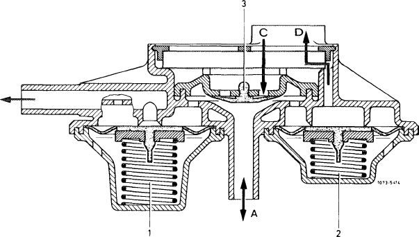
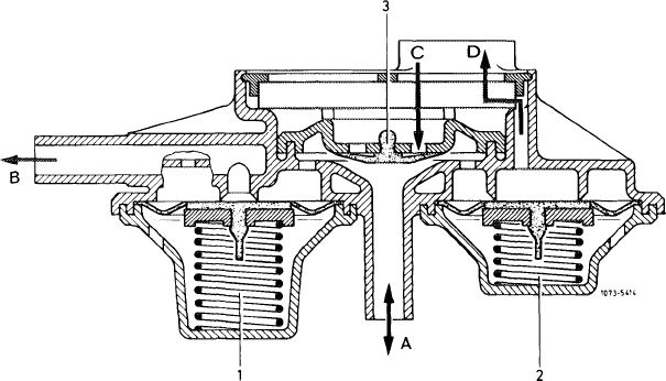
The negative vent valve (1) opens at slight overpressure. The evaporation vapors are flowing via a negative vent valve (1, direction B) into a line toward engine. The line enters into cylinder crankcase at connection point.
The pressure relief valve (2) opens as a safety valve in the event of overpressure in fuel evaporation system. The fuel vapors are bled directly into the open air.
The positive vent valve (3) opens whenever cooling down of fuel tank results in a vacuum.
|
||||
|
|
||||
|
1 Negative vent valve
2 Pressure relief valve
3 Positive vent valve
A To valve/to expansion tank
B To crankcase
C Fresh air inlet
D Outlet pressure relief valve
|
B
|
|||
|
|
||||
|
47.2 lb-800/2
|
||||
|
|
||||
|
|
||||
|
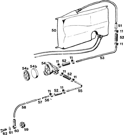
Model 114 Fuel evaporation control system
1472-7781
|
||||
|
|
||||
|
starting January 1973 up to production model year 1976 1973, 1974 Federal
|
||||
|
|
||||
|
11
50 51 52 53 54
|
Hose clamp
Fuel expansion tank
Connecting pipe
Fuel hose
Negative venting line
Valve system
|
|||
|
|
||||
|
555666
|
54a Cover 54b Filter 55 Negative vent line
Connecting pipe
Throttle
Negative vent line
Closing plug
Ring fitting
Sealing ring
Hollow screw
|
|||
|
|
||||
|
|
||||
|
47.2 lb-800/3
|
||||
|
|
||||
|
|
||||
|
£*> California 1974 and T) 1976
|
||||
|
|
||||
|
A fuel evaporation control system has been installed to improve emissions which are not directly connected with engine combustion.
|
||||
|
|
||||
|
Components of fuel evaporation control system
|
 |
|||
|
Valve system
The valve system is mounted underneath vehicle in level of rear legroom.
The valve system comprises three valves:
1. Negative vent valve
2. Pressure relief valve
3. Positive vent valve , Protective box
3 Valve system
|
||||
|
|
||||
|
The negative vent valve opens at a slight overpressure. The evaporation vapors are flowing via negative vent valve (1, direction B) into the line toward charcoal canister.
The pressure relief valve opens as a safety valve in the event of an overpressure in fuel evaporation system. The fuel vapors are bled directly into the open air.
The positive vent valve opens whenever cooling down of fuel tank results in a vacuum.
|
||||
|
|
||||
|
1 Negative vent valve
2 Pressure relief valve
3 Positive vent valve
A To valve/to expansion tank
B To charcoal canister
C Fresh air inlet
D Outlet pressure relief valve
|
 |
|||
|
|
||||
|
47.2 lb-800/4
|
||||
|
|
||||
|
|
||||
|
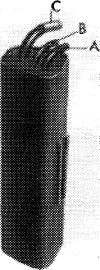
Charcoal canister
The fuel evaporation vapors from fuel tank and from float chamber are stored in charcoal canister and are drawn again out of canister when driving.
|
 |
107-9131
|
||
|
A Tank vent connection
B Draw-off valve connection
C Float chamber-positive vent valve connection
|
||||
|
|
||||
|
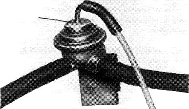
Draw-off valve (purge valve)
The draw-off valve (purge valve) controls the volume of the fuel evaporation gases, which are drawn off by way of a connection in front of carburetor throttle valve depending on throttle valve position.
|
38
|
|||
|
|
||||
|
, 107-8974
|
||||
|
|
||||
|
Operation
|
||||
|
|
||||
|
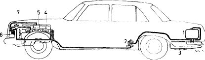
Function diagram
|
||||
|
|
||||
|
1 Expansion tank
2 Valve system
3 Fuel tank
4 Intake pipe
5 Carburetor with positive vent valve
6 Charcoal canister
7 Draw-off valve (purge valve)
|
 |
|||
|
|
||||
|
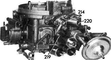
The fuel evaporation gases from fuel tank and from float chamber of carburetor are stored in charcoal canister when the engine is stopped, and are drawn from charcoal canister when the engine is running, depending on intake pipe vacuum.
The fuel evaporation vapors are routed directly into charcoal canister.
|
 |
|||
|
|
||||
|
214 Float chamber positive vent valve
219 Vacuum connection
220 Negative vent connection
|
107-10093
|
|||
|
|
||||
|
47.2 lb-800/5
|
||||
|
|
||||
|
|
|||
|
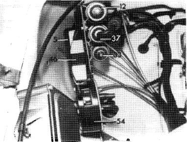
The fuel evaporation vapors from float chamber are flowing to charcoal canister only when the engine is stopped and the float chamber positive vent valve is open and are stored in charcoal canister.
|
507-10040,
|
||
|
With the engine running, the switchover valve (37) is energized and the diaphragm of the float chamber positive vent valve is provided with a vacuum, the valve will close and interrupt the connection to charcoal canister.
|
|||
|
|
|||
|
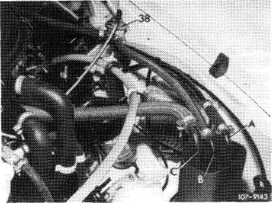
In dependence of the throttle valve position of the I. stage of the carburetor the diaphragm of the draw-off valve (38) is provided with a vacuum, the valve opens.
The intake pipe vacuum will draw the stored vapors from charcoal canister for burning.
|
 |
||
|
38 Draw-off valve (purge valve)
A Tank vent connection
B Draw-off valve connection
C Float chamber-positive vent valve connection
|
|||
|
|
|||
|
47.2 lb-800/6
|
|||
|
|
|||
|
|
||||
|
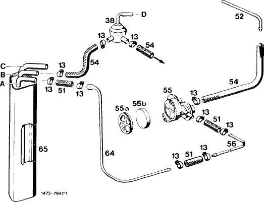
Fuel evaporation control system
© 1974 California, 1975/76 Federal and California
CD 1976
|
||||
|
|
||||
|
13 Hose clamp
38 Draw-off valve (purge valve)
51 Fuel hose
52 Negative vent line from fuel tank
54 Fuel hose
55 Valve system 55a Cover
55b Filter
56 Negative vent line
64 Negative vent line
65 Charcoal canister
A Tank vent connection
B Draw-off valve connection
C Float chamber-positive vent valve connection
D Vacuum line
Arrow = draw-off connection carburetor
|
 |
13%
|
||
|
|
||||
|
47.2 lb-800/7
|
||||
|
|
||||