Cleaning carburetor
|
|
|||||
|
07.2—190 Cleaning carburetor
|
|||||
|
|
|||||
|
Identification: Information plate in national language on cross member in front of radiator or on cylinder head cover. Adjust engines according to data of respective exhaust gas information plate.
|
|||||
|
|
|||||
|
Testing and adjusting values
|
|||||
|
|
|||||
|
National version
|
Idle speed 1/min
|
Idle speed emission value % CO
|
|||
|
|
|||||
|
up to 1976
|
max. 1.5
|
||||
|
|
|||||
|
1976
|
800-900
|
||||
|
|
|||||
|
max. 1.0 without air injection
|
|||||
|
|
|||||
|
1976
|
|||||
|
|
|||||
|
1973
|
|||||
|
|
|||||
|
750-900
|
up to 1.5
|
||||
|
|
|||||
|
1974 Federal
|
|||||
|
|
|||||
|
1974 California
|
700-900
|
6—8 without air injection
|
|||
|
|
|||||
|
1975/76
|
800-900
|
max. 1.0 without air injection
|
|||
|
|
|||||
|
Vacuum governor1)
|
|||||
|
|
|||||
|
National version
|
Engine speed
Vacuum hose pulled off
1/min
|
Engine speed
Driving position engaged
1/min
|
|||
|
|
|||||
|
without
TN choke
|
with
TN choke
|
||||
|
|
|||||
|
1976
|
|||||
|
|
|||||
|
1976
|
|||||
|
|
|||||
|
1700-1900
|
600-700
|
||||
|
|
|||||
|
1973/74
|
1200-1400
|
||||
|
|
|||||
|
1975/76
|
|||||
|
|
|||||
|
M When all auxiliary units are engaged, the engine should still run smoothly.
|
|||||
|
|
|||||
|
07.2.2 la-190/1
|
|||||
|
|
|||||
|
|
|||||||||||||
|
Float level
|
|||||||||||||
|
|
|||||||||||||
|
Float version
|
Float level1)
|
||||||||||||
|
|
|||||||||||||
|
Flat roof float
|
-2 to 6 mm3)
|
||||||||||||
|
|
|||||||||||||
|
Hip roof float and fuel return valve without fuel pressure regulation
|
0 mm2)
|
||||||||||||
|
|
|||||||||||||
|
Hip roof float and fuel return valve with fuel pressure regulation
|
+ 2 mm2)
|
||||||||||||
|
|
|||||||||||||
|
!) Measure from parting surface without gasket.
2) In the event of starting or bypass faults, set 2 mm higher.
3) Under parting surface.
|
|||||||||||||
|
|
|||||||||||||
|
Carburetor line-up
|
|||||||||||||
|
|
|||||||||||||
|
National version
|
1976
|
s) 1976
|
<&«$> 1973
(usa) 1974 Federal
|
(usa) 1974 California
|
1975/76
|
||||||||
|
|
|||||||||||||
|
Carburetor designation
|
Solex two-stage downdraft carburetor 4 A 1
|
||||||||||||
|
|
|||||||||||||
|
Carburetor stage
|
Stage I Stage 11
|
Stage I Stage II
|
Stage I Stage 11
|
Stage I Stage II
|
Stage I Stage 11
|
||||||||
|
|
|||||||||||||
|
Main jet
|
X 105 –
|
X 105 –
|
X 100
|
X 112.5 –
|
X1052) –
|
||||||||
|
|
|||||||||||||
|
Jet needle
|
A7
|
A4
|
A4
|
A5
|
A7
|
||||||||
|
|
|||||||||||||
|
Idle speed fuel jet
|
47.51) –
|
451!
|
453)
|
453)
|
47.51)
|
||||||||
|
|
|||||||||||||
|
Idle speed air jet
|
102.51) –
|
102.51) –
|
110
|
100
|
102.51) –
|
||||||||
|
|
|||||||||||||
|
M Combination jet
2) Model year 1975, size 100
3) Pressed-in, cannot be disassembled.
|
|||||||||||||
|
|
|||||||||||||
|
Special tools
|
|||||||||||||
|
|
|||||||||||||
|
Oil telethermometer
|
 |
116 589 27 21 00
|
|||||||||||
|
|
|||||||||||||
|
Digital tester
|
 |
001 589 54 21 00
|
|||||||||||
|
|
|||||||||||||
|
07.2.2 la-190/2
|
|||||||||||||
|
|
|||||||||||||
|
|
|||||
|
Connecting cable 3 m long
|
 |
000 589 04 90 00
|
|||
|
|
|||||
|
Intermediate plug (adaptor)
|
 |
000 589 72 63 00
|
|||
|
|
|||||
|
Trigger
|
 |
000 589 71 63 00
|
|||
|
|
|||||
|
Conventional tools
|
|||||
|
|
|||||
|
Revolution counter and CO measuring instrument
|
|||||
|
|
|||||
|
Self-made tool
|
|||||
|
|
|||||
|
Puller
|
refer to Fig. item 9
|
||||
|
|
|||||
|
Cleaning
|
 |
||||
|
1 Remove air filter.
2 Thoroughly clean outside of carburetor.
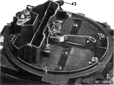
3 Loosen all fastening nuts and screws on carburetor cover. Pull off lock (43) and disconnect choke rod. Unscrew air filter fastening screw.
|
|||||
|
|
|||||
|
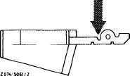
Attention!
Press off carburetor cover only at pressing-off point.
|
 |
||||
|
|
|||||
|
07.2.2 la-190/3
|
|||||
|
|
|||||
|
|
|||
|
4 Clean filter strainer with compressed air.
|
 |
||
|
|
|||
|
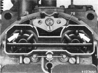
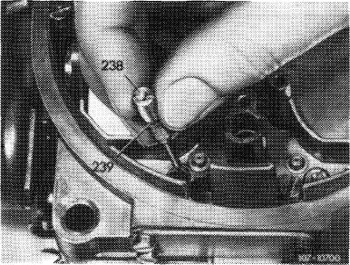
5 Unscrew idle speed jets or combination jet (238). Blow out jet and duct with compressed air.
|
 |
||
|
78 Idle speed air jet
|
|||
|
|
|||
|
Combination jet
238 Idle speed and idle speed fuel jet
239 O-ring
|
 |
||
|
|
|||
|
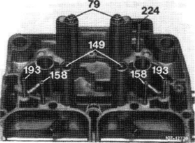
6 Remove main jets (79). Blow out all ducts, bores, riser pipes and jets with compressed air.
Attention!
Do not clean jets with metallic items (e.g. wire, drill).
|
 |
||
|
79 Main jets stages I 149 Jet needles stage II 158 Riser pipes bypass system stage 11 193 Riser pipes starting mixture enrichment 224 Riser pipe TN choke (thermostatically controlled bypass choke)
|
|||
|
|
|||
|
07.2.2 la-190/4
|
|||
|
|
|||
|
|
|||
|
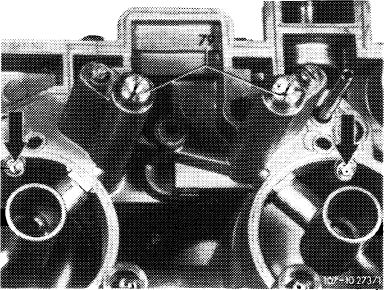
7 Blow out injection bores (arrows) of accelerating pump with compressed air and check for unobstructed passage (clean injection bores with a 0.5 mm drill, if required).
Check jet line-up. Install all parts.
|
 |
||
|
|
|||
|
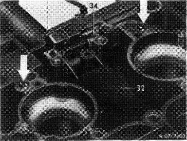
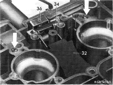
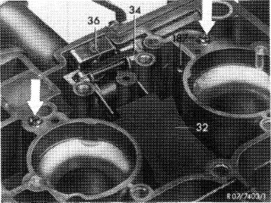
8 Remove holddown (34), float (32) with float needle valve.
|
 |
||
|
|
|||
|
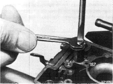
9 Pull out closing plug for intake port (suction duct) of accelerating pump with self-made puller. Lift valve ball out of duct (e.g. welding wire with grease).
|
 |
||
|
|
|||
|
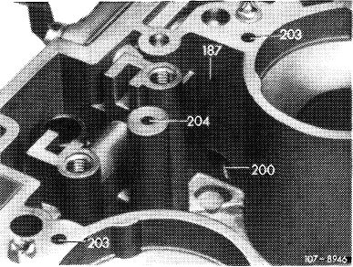
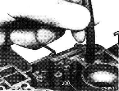
10 Clean float chamber and ducts (200, 203, 204, 187) with compressed air.
|
 |
||
|
187 Vent bore
200 Intake port
203 Idle speed mixture ducts
204 Vacuum bore for controlling enrichment
|
|||
|
|
|||
|
07.2.2 la-190/5
|
|||
|
|
|||
|
|
|||
|
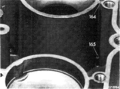
11 Clean feed bores (165) and reserve chambers (164) with compressed air.
|
 |
||
|
164 Reserve chamber for bypass system stage II 165″ Feed bore for reserve chamber stage II
|
|||
|
|
|||
|
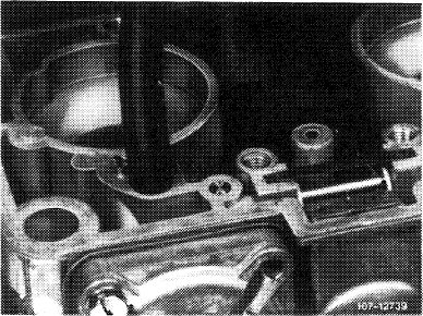
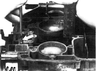
12 Check suction valve for leaks. For this purpose, install valve ball (5 mm steel ball). Fill float chamber with fuel. Slip suitable hose over suction duct (intake port), keep both delivery valves (arrow) closed, on carburetors with vent bore (187) also keep these bores closed and blow into hose. No or only individual air bubbles should come out of intake bore and enter float chamber.
|
 |
||
|
|
|||
|
Attention!
In the event of leaks, knock lightly against suction valve seat with steel ball (5 mm dia.). Insert new steel ball and check once again for leaks. Then close intake port (suction duct).
|
 |
||
|
187 Vent bore
Arrow = delivery valve
|
|||
|
|
|||
|
13 Check delivery valves for leaks. For this purpose, slip suitable hose over a delivery valve, keep other delivery valve closed, on carburetors with vent bore (187) keep this bore also closed and blow into hose. No or only individual air bubbles should come out of suction bore (200) and enter float chamber. Then check opposite delivery valve.
Attention!
In the event of leaks, knock balls of delivery valves „lightly” against their seat.
|
 |
||
|
|
|||
|
07.2.2 la-190/6
|
|||
|
|
|||
|
|
|||
|
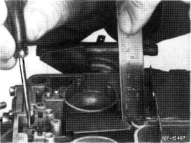
14 Check float level and adjust, if required. For this purpose, push connecting web (arrow) up to noticeable stop in downward direction and check float level without gasket.
Attention!
To avoid measuring faults, make sure that the float shaft rests on base of housing during test.
|
 |
||
|
Measuring float level with flat roof float
|
|||
|
|
|||
|
Measuring float level with hip roof float
|
 |
||
|
|
|||
|
Correct float level, if required, by rebending at specified bending point (arrow).
|
 |
||
|
|
|||
|
15 Attach float needle with wire clip on float arm in such a manner that the open side of clip points in driving direction.
16 Install float (32), making sure that the float shaft rests on base of recesses. Insert holddown (34). Holddown should project slightly over parting surface. Rebend, if required.
17 Mount carburetor cover with new gasket.
18 Mount air filter.
19 Adjust idle speed (07.2-100).
|
 |
||
|
|
|||
|
07.2.2 la-190/7
|
|||
|
|
|||