Checking fuel pressures and for internal leaks
|
|
||||||||||||||||||||||||||||||||||||||||||||||||||||||||||||
|
07.3—120 Checking fuel pressures and for internal leaks
|
||||||||||||||||||||||||||||||||||||||||||||||||||||||||||||
|
|
||||||||||||||||||||||||||||||||||||||||||||||||||||||||||||
|
A. Standard version
|
||||||||||||||||||||||||||||||||||||||||||||||||||||||||||||
|
|
||||||||||||||||||||||||||||||||||||||||||||||||||||||||||||
|
Test values in bar gauge pressure
|
||||||||||||||||||||||||||||||||||||||||||||||||||||||||||||
|
|
||||||||||||||||||||||||||||||||||||||||||||||||||||||||||||
|
||||||||||||||||||||||||||||||||||||||||||||||||||||||||||||
|
|
||||||||||||||||||||||||||||||||||||||||||||||||||||||||||||
|
l) If control pressure is not attained, check intake manifold vacuum (section „Checking control pressure at idle with engine at operating temperature”).
|
||||||||||||||||||||||||||||||||||||||||||||||||||||||||||||
|
|
||||||||||||||||||||||||||||||||||||||||||||||||||||||||||||
|
Special tools
|
||||||||||||||||||||||||||||||||||||||||||||||||||||||||||||
|
|
||||||||||||||||||||||||||||||||||||||||||||||||||||||||||||
|
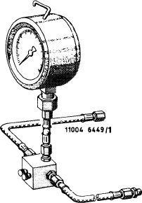
Pressure tester
|
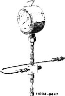 |
102 589 00 21 00
|
||||||||||||||||||||||||||||||||||||||||||||||||||||||||||
|
|
||||||||||||||||||||||||||||||||||||||||||||||||||||||||||||
|
Clamp for hose lines
|
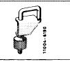 |
000 589 40 37 00
|
||||||||||||||||||||||||||||||||||||||||||||||||||||||||||
|
|
||||||||||||||||||||||||||||||||||||||||||||||||||||||||||||
|
Conventional tools
|
||||||||||||||||||||||||||||||||||||||||||||||||||||||||||||
|
|
||||||||||||||||||||||||||||||||||||||||||||||||||||||||||||
|
Voltmeter, ohmmeter
|
||||||||||||||||||||||||||||||||||||||||||||||||||||||||||||
|
|
||||||||||||||||||||||||||||||||||||||||||||||||||||||||||||
|
Screw driver element 992—T 30
|
e.g. made by Hazet, D-5630 Remscheid
|
|||||||||||||||||||||||||||||||||||||||||||||||||||||||||||
|
|
||||||||||||||||||||||||||||||||||||||||||||||||||||||||||||
|
07.3.2 I la—120/1 F2
|
||||||||||||||||||||||||||||||||||||||||||||||||||||||||||||
|
|
||||||||||||||||||||||||||||||||||||||||||||||||||||||||||||
|
|
|||
|
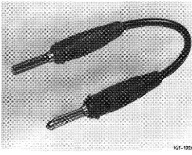
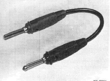
Self-made tool
|
|||
|
|
|||
|
Contact bridge
|
 |
||
|
|
|||
|
Note:
|
|||
|
|
|||
|
Prior to working on injection system, check firing point, spark plugs and idle speed adjustment.
Perform leak test only in the event of complaints about hot starting.
After stopping the engine, the fuel pressure should still amount to 2.5 bar gauge pressure after 30 minutes.
|
|||
|
|
|||
|
Visual checkup
|
|||
|
|
|||
|
1 Remove air cleaner.
|
|||
|
|
|||
|
2 Check all fuel connections for leaks.
|
|||
|
|
|||
|
07.3.2 lla-120/2 F2
|
|||
|
|
|||
|
|
|||
|
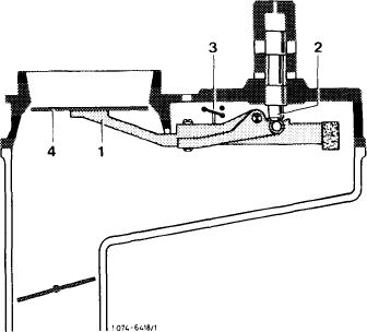
3 Check for easy operation of adjusting lever (1) in air flow sensor and control piston (2) in fuel distributor For this purpose, proceed as follows:
|
 |
||
|
Mixture controller with safety switch
Pull plug from safety switch (3), switch-on ignition for a short moment to build up control pressure.
|
|||
|
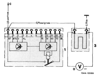
Mixture controller without safety switch
Pull off fuel pump relay and bridge the two jacks for a moment to build up control pressure.
Prior to September 1981: Jacks 1 and 2. Starting September 1981: Jacks 7 and 8.
Push air flow sensor (4) down manually. A uniform resistance should then be felt along entire path. No resistance should be felt during fast upward moment, since the slowly following control piston lifts off from adjusting lever. If the upward movement is slow, a control piston should closely follow.
|
|||
 |
|||
|
|
|||
|
4 Check control piston in fuel distributor for leaks. Push air flow sensor for a short moment completely down and hold in this position, no fuel should then show up in air guide housing.
If fuel emerges, replace fuel distributor (07.3—205).
|
|||
|
|
|||
|
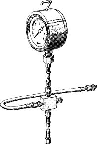
Connecting pressure measuring device
|
|||
|
|
|||
|
The pressure measuring device remains connected for all pressure measurements.
The pressure measuring device 102 589 00 21 00 now remains equipped with a valve screw on three-way vaive only.
|
|||
|
|
|||
|
07.3.2 lla-1 20/3 F2
|
|||
|
|
|||
|
|
|||
|
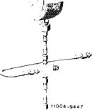
To relieve sealing rings, keep valve screw or valve screws always open. Connections of three-way valve are numbered.
|
 |
||
|
Pressure measuring device 1st version
Connection 1 = hose line on fuel distributor
Connection 2 = hose line on pressure gauge
Connection 3 = hose line on released control pressure line
|
|||
|
|
|||
|
Pressure measuring device 2nd version
Connection A = hose line on fuel distributor
Connection B = hose line on released control pressure line
|
11004 -9447M
|
||
|
|
|||
|
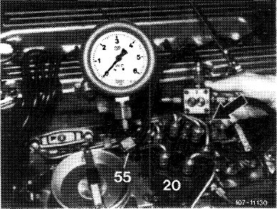
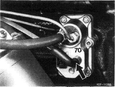
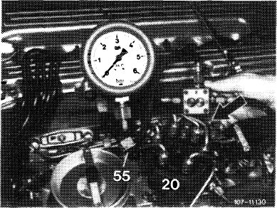
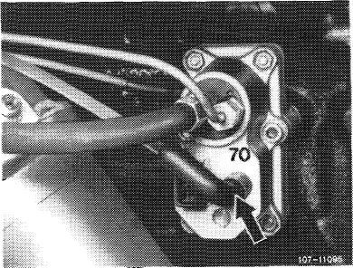
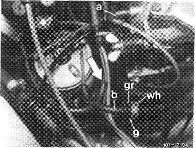
1 Unscrew control pressure line (arrow) on fuel distributor (20), while catching fuel with a rag.
2 Connect hose line from connection 1 or A to fuel distributor (20) and hose line of connection 3 or B to control pressure line (arrow).
|
 |
||
|
|
|||
|
Checking control pressure at idle in cold engine
|
|||
|
|
|||
|
3 Open valve screw or valve screws on pressure measuring device.
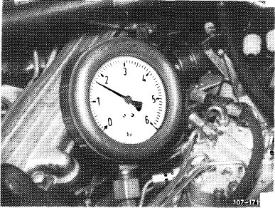
4 Run engine at idle and immediately read control pressure.
|
|||
|
|
|||
|
07.3.2 I la—120/4 F2
|
|||
|
|
|||
|
|
|||
|
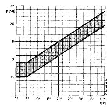
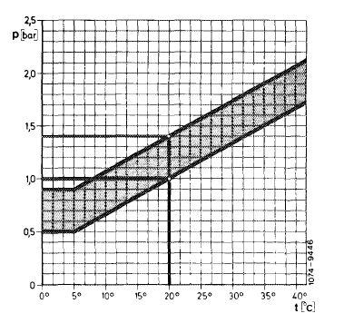
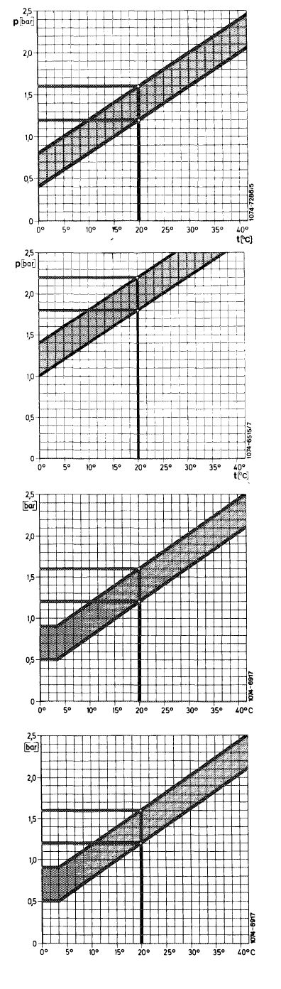
Take nominal pressure according to ambient temperature from control pressure diagram. If the nominal value is not attained, recondition system pressure regulator (07.3—210), or check input strainer in warm-up compensator. Replace warm-up compensator, if required.
Example:
Warm-up compensator with Bosch end no. 010 and
057:
Ambient temperature +20 °C = 1.0—1.5 bar gauge
pressure.
Warm-up compensator with Bosch end no. 103: Ambient temperature +20 °C = 1.0—1.4 bar gauge pressure.
|
 |
||
|
|
|||
|
5 Check stabilizing time of warm-up compensator. Read initial control pressure at +20 °C. The stabilizing time at 3.4 bar gauge pressure should be within tolerance. Additional electric consumers switched off, minimum voltage 12 Volts.
Example:
Stabilizing time at +20 °C
Warm-up compensator with Bosch end no. 010 = 3—6 minutes
Warm-up compensator with Bosch end no. 057 and 103 = 2-4 minutes.
Checking system pressure at idle with engine cold or at operating temperature
|
 |
||
|
|
|||
|
6 Close valve screw on pressure measuring device. When measuring pressure, with 2 valve screws, close valve screw at connection 3.
7 The system pressure should amount to 5.0—5.6 bar gauge pressure.
|
|||
|
|
|||
|
8 If the system pressure of 5.0—5.6 bar gauge pressure is not attained or exceeded, perform the following checkups:
a) Check delivery capacity of fuel pump (07.3—130).
b) Recondition system pressure regulator (07.3—210).
c) Check fuel return flow line for passage.
|
|||
|
|
|||
|
9 Re-open valve screw.
|
|||
|
|
|||
|
07.3.2 I la—1 20/5 F2
|
|||
|
|
|||
|
|
|||
|
Checking control pressure at idle with engine at operating temperature
|
|||
|
|
|||
|
10 Open both valve screws or valve screw on pressure measuring device.
11 Control pressure should increase to 3.4—3.8 or 3.6—4.0 bar gauge pressure (warm-up compensator stabilized).
If the control pressure of 3.4-3.8 or 3.6-4.0 bar gauge pressure is not attained, perform the following checkups.
|
|||
|
|
|||
|
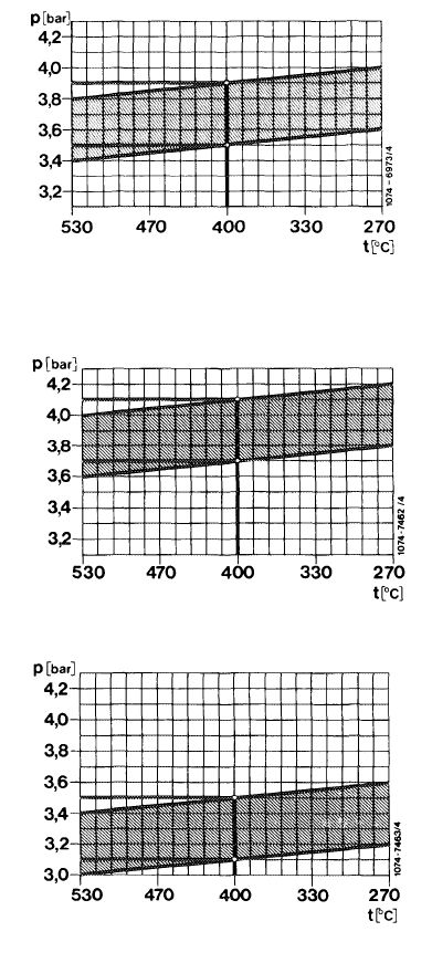
Engine 110.984/985/986/987
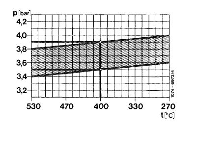
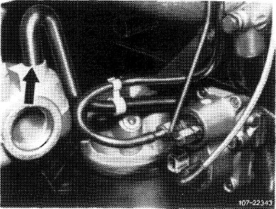
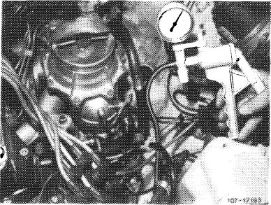
a) Check intake manifold vacuum. For this purpose, pull off vacuum hose (arrow in fig. item 12) on warm-up compensator and attach a T-fitting for pressure gauge.
Read intake manifold vacuum and transfer to vacuum diagram.
|
 |
||
|
Example:
Intake manifold vacuum 400 mbar = 3.5—3.9 bar gauge pressure.
Engine 110.988/989/990
The control pressure is not influenced by vacuum from change on warm-up compensator.
b) Test voltage on warm-up compensator with engine running. Pull electrical connection from warm-up compensator and test voltage. Minimum voltage
12 Volts (without electrical consumers).
c) Test heater coil with an ohmmeter for passage. Resistance: 20-40 £1.
Replace warm-up compensator in the event of an interruption.
d) If the control pressure is above 3.6 or 3.8 bar gauge pressure, recondition system pressure regulator (07.3-210).
|
|||
 |
|||
|
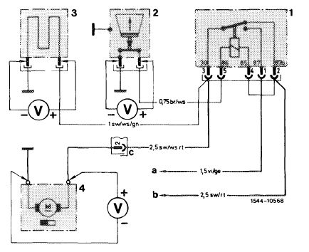
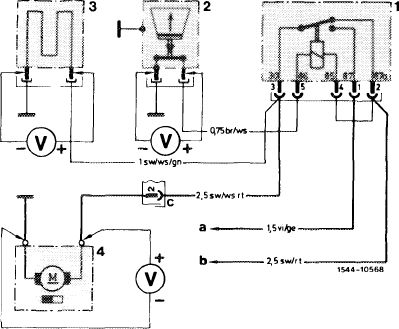
Mixture controller with safety switch
1 Fuel pump relay
2 Safety switch — air flow sensor plate
3 Warm-up compensator
4 Fuel pump
a Terminal 50 (starting) b Terminal 15/54 (ignition) c Plug connection 14-point tail lamp unit harness
|
|||
|
|
|||
|
07.3.2 I la—1 20/6 F2
|
|||
|
|
|||
|
|
|||
|
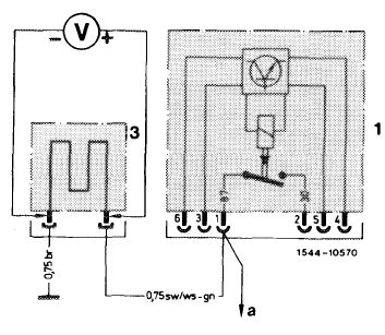
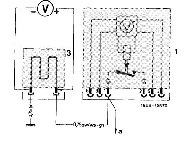
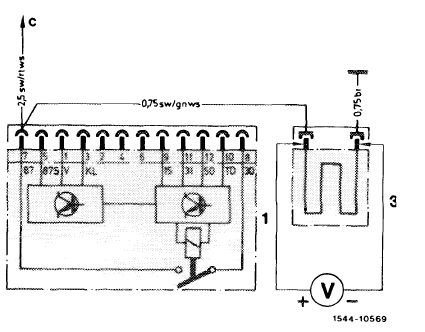
Mixture controller without safety switch
|
 |
||
|
Prior to September 1981
1 Fuel pump relay
3 Warm-up compensator
a To fuel pump
|
|||
|
|
|||
|
Starting September 1981
1 Fuel pump relay
3 Warm-up compensator
c To fuel pump
|
 |
||
|
|
|||
|
12 Check full load enrichment. For this purpose, pull vacuum hose (arrow) from warm-up compensator or at intake manifold, control pressure should then drop to 2.8—3.2 bar gauge pressure.
If a control pressure of 2.8—3.2 bar gauge pressure is not attained, replace warm-up compensator.
|
 |
||
|
|
|||
 |
|||
|
|
|||
|
07.3.2 lla-1 20/7 F2
|
|||
|
|
|||
|
|
|||
|
Checking fuel distributor and fuel pump for leaks
13 Stop engine. Control pressure will then drop below opening pressure of injection valves (approx. 2.8 bar gauge pressure).
14 If the control pressure drops immediately to 0 bar gauge pressure, replace check valve on fuel pump or subsequently install.
15 If the pressure drops slowly, unscrew fuel return line on fuel distributor. Fuel will emerge in the event of a leak on regulator piston or pressure compensating valve. If there is more than 1 drop in 4 seconds, recondition system pressure regulator or pressure compensating valve (07.3—210).
16 Check fuel reservoir for leaks (not included in time rate). For this purpose, disconnect leak line between fuel reservoir and intake damper.
17 Loosen leak line on intake damper and pull off. Loosen clamp, pressureless leaking is permissible. Replace fuel reservoir, if required (07.3—270).
|
|||
|
|
|||
|
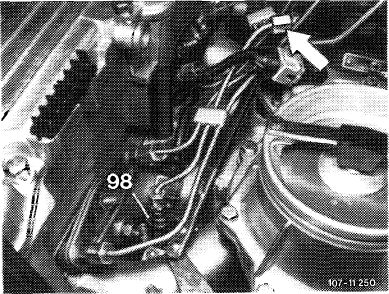
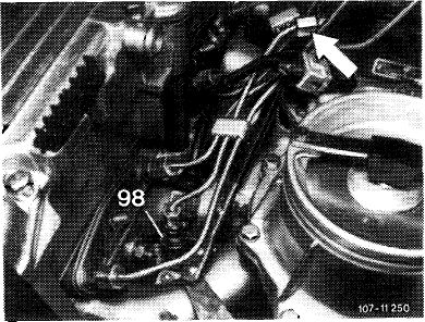
18 Check cold-starting valve (98) for leaks. For this purpose, remove cold-starting valve (07.3—125, section Checking for leaks).
19 Close pressure measuring device, while catching fuel with a rag.
20 Connect fuel lines, run engine once again and check all fuel connections for leaks.
|
 |
||
|
|
|||
|
07.3.2 Ha—1 20/8 F2
|
|||
|
|
|||
|
|
|||||||||||||||||||||||||||||||||||||||||||||||||||||||||||||
|
B. National version (aus)
|
|||||||||||||||||||||||||||||||||||||||||||||||||||||||||||||
|
|
|||||||||||||||||||||||||||||||||||||||||||||||||||||||||||||
|
Test values in bar gauge pressure
|
|||||||||||||||||||||||||||||||||||||||||||||||||||||||||||||
|
|
|||||||||||||||||||||||||||||||||||||||||||||||||||||||||||||
|
|||||||||||||||||||||||||||||||||||||||||||||||||||||||||||||
|
|
|||||||||||||||||||||||||||||||||||||||||||||||||||||||||||||
|
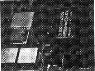
(aus) starting 1977
Identification: Label silver.
(T) starting 1977
Identification: Label blue.
|
|||||||||||||||||||||||||||||||||||||||||||||||||||||||||||||
|
|
|||||||||||||||||||||||||||||||||||||||||||||||||||||||||||||
|
030 056 057
|
5.0-5.6
|
3.4-3.8
|
2.8-3.2
|
||||||||||||||||||||||||||||||||||||||||||||||||||||||||||
|
|
|||||||||||||||||||||||||||||||||||||||||||||||||||||||||||||
|
-1980
Identification: Label in Japanese language.
|
|||||||||||||||||||||||||||||||||||||||||||||||||||||||||||||
|
|
|||||||||||||||||||||||||||||||||||||||||||||||||||||||||||||
|
031
|
5.0-5.6
|
3.0-3.4
|
2.8-3.2
|
||||||||||||||||||||||||||||||||||||||||||||||||||||||||||
|
|
|||||||||||||||||||||||||||||||||||||||||||||||||||||||||||||
|
(@) 1977-1979
Identification: Label black.
Identification: 1979 label Federal black, California yellow.
|
|||||||||||||||||||||||||||||||||||||||||||||||||||||||||||||
|
|
|||||||||||||||||||||||||||||||||||||||||||||||||||||||||||||
|
|||||||||||||||||||||||||||||||||||||||||||||||||||||||||||||
|
|
|||||||||||||||||||||||||||||||||||||||||||||||||||||||||||||
|
If the control pressure is not attained, check intake manifold vacuum (refer to section „Checking control pressure at idle with engine at operating temperature”).
|
|||||||||||||||||||||||||||||||||||||||||||||||||||||||||||||
|
|
|||||||||||||||||||||||||||||||||||||||||||||||||||||||||||||
|
07.3.2 Ma—1 20/9 F2
|
|||||||||||||||||||||||||||||||||||||||||||||||||||||||||||||
|
|
|||||||||||||||||||||||||||||||||||||||||||||||||||||||||||||
|
|
||||||||||||||||||||||||||||||||||||||||||||||||||||||||||||||||||||||||||||||
|
||||||||||||||||||||||||||||||||||||||||||||||||||||||||||||||||||||||||||||||
|
|
||||||||||||||||||||||||||||||||||||||||||||||||||||||||||||||||||||||||||||||
|
(T) starting 1981
Identification: Label in Japanese language.
(@) 1980/81
Identification: Label Federal black.
|
||||||||||||||||||||||||||||||||||||||||||||||||||||||||||||||||||||||||||||||
|
|
||||||||||||||||||||||||||||||||||||||||||||||||||||||||||||||||||||||||||||||
|
067
|
5.0-5.8
|
3.4-3.8
|
1.4-1.8
|
|||||||||||||||||||||||||||||||||||||||||||||||||||||||||||||||||||||||||||
|
|
||||||||||||||||||||||||||||||||||||||||||||||||||||||||||||||||||||||||||||||
|
) If the control pressure is not attained, check intake manifold vacuum (refer to section „Checking control pressure at idle with engine at operating temperature”).
|
||||||||||||||||||||||||||||||||||||||||||||||||||||||||||||||||||||||||||||||
|
|
||||||||||||||||||||||||||||||||||||||||||||||||||||||||||||||||||||||||||||||
|
Special tools
|
||||||||||||||||||||||||||||||||||||||||||||||||||||||||||||||||||||||||||||||
|
|
||||||||||||||||||||||||||||||||||||||||||||||||||||||||||||||||||||||||||||||
|
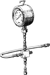
Pressure measuring device
|
 |
102 589 00 21 00
|
||||||||||||||||||||||||||||||||||||||||||||||||||||||||||||||||||||||||||||
|
|
||||||||||||||||||||||||||||||||||||||||||||||||||||||||||||||||||||||||||||||
|
Clamp for hose lines
|
 |
000 589 40 37 00
|
||||||||||||||||||||||||||||||||||||||||||||||||||||||||||||||||||||||||||||
|
|
||||||||||||||||||||||||||||||||||||||||||||||||||||||||||||||||||||||||||||||
|
Conventional tools
|
||||||||||||||||||||||||||||||||||||||||||||||||||||||||||||||||||||||||||||||
|
|
||||||||||||||||||||||||||||||||||||||||||||||||||||||||||||||||||||||||||||||
|
Voltmeter/oh mmeter
|
||||||||||||||||||||||||||||||||||||||||||||||||||||||||||||||||||||||||||||||
|
|
||||||||||||||||||||||||||||||||||||||||||||||||||||||||||||||||||||||||||||||
|
Screw driver element 992—T 30
|
e.g. made by Hazet, D-5630 Remscheid
|
|||||||||||||||||||||||||||||||||||||||||||||||||||||||||||||||||||||||||||||
|
|
||||||||||||||||||||||||||||||||||||||||||||||||||||||||||||||||||||||||||||||
|
07.3.2 lla-120/10
|
F 2
|
|||||||||||||||||||||||||||||||||||||||||||||||||||||||||||||||||||||||||||||
|
|
||||||||||||||||||||||||||||||||||||||||||||||||||||||||||||||||||||||||||||||
|
|
|||
|
Self made tool
|
|||
|
|
|||
|
Contact bridge
|
 |
||
|
|
|||
|
Note
|
|||
|
|
|||
|
Prior to working on injection system, check firing point, spark plugs and idle speed adjustment.
Perform leak test only in the event of complaints about hot starting.
After stopping engine, the fuel pressure should still amount to 2.5 bar gauge pressure after 30 minutes.
|
|||
|
|
|||
|
Visual checkup
|
|||
|
|
|||
|
1 Remove air cleaner.
|
|||
|
|
|||
|
2 Check all fuel connections for leaks.
|
|||
|
|
|||
|
07.3.2 I la—1 20/11
|
F 2
|
||
|
|
|||
|
|
||||
|
3 Check for easy operation of adjusting lever (1) in air flow sensor and control piston (2) in fuel distributor. For this purpose, proceed as follows:
|
 |
|||
|
Mixture controller with safety switch
Pull plug from safety switch (3), switch-on ignition for a short moment to build up control pressure.
|
||||
|
Mixture controller without safety switch
Pull off fuel pump relay and bridge the two jacks for a moment to build up control pressure.
Up to model year 1981: Jacks 1 and 2 Starting model year 1982: Jacks 7 and 8.
Push air flow sensor (4) down manually. A uniform resistance should then be felt along entire path. No resistance should be felt during fast upward movements, since the slowly following control piston lifts off from adjusting lever. If the upward movement is slow, a control piston should closely follow.
|
||||
 |
||||
|
|
||||
|
4 Check control piston in fuel distributor for leaks. Push air flow sensor for a short moment completely down and hold in this position, no fuel should then show up in air guide housing.
If fuel emerges, replace fuel distributor (07.3—205).
|
||||
|
|
||||
|
Connecting pressure measuring device
|
||||
|
|
||||
|
The pressure measuring device remains connected for all pressure measurements.
The pressure measuring device 102 589 00 21 00 now remains equipped with a valve screw on three-way valve only.
|
||||
|
|
||||
|
07.3.2 lla-120/12
|
F 2
|
|||
|
|
||||
|
|
||||
|
To relieve sealing rings, keep valve screw or valve screws always open. Connections of three-way valve are numbered.
|
 |
|||
|
Pressure measuring device 1st version
Connection 1 = hose line on fuel distributor
Connection 2= hose line on pressure gauge
Connection 3= hose line on released control pressure line
|
||||
|
|
||||
|
Pressure measuring device 2nd version
Connection A = hose line on fuel distributor
Connection B = hose line on released control pressure line
|
11004-9447/1
|
|||
|
|
||||
|
1 Unscrew control pressure line (arrow) on fuel distributor (20), while catching fuel with a rag.
2 Connect hose line from connection 1 or A to fuel distributor (20) and hose line of connection 3 or B to control pressure line (arrow).
|
 |
|||
|
|
||||
|
Checking control pressure at idle in cold engine
|
||||
|
|
||||
|
3 Open valve screw or valve screws on pressure measuring device.
4 Run engine at idle and immediately read control pressure.
Take nominal pressure according to ambient temperature from control pressure diagram. If the nominal value is not attained, recondition system pressure regulator (07.3—210), or check input strainer in warm-up compensator. Replace warm-up compensator, if required.
|
||||
|
|
||||
|
07.3.2 Ma—1 20/13
|
F 2
|
|||
|
|
||||
|
|
|||
|
T)(usa) Federal and California 1976/77
|
 |
||
|
Warm-up compensator Bosch end no.
030 (aus) (V) (usa) Federal
031 CO (usa) California
|
|||
|
Example:
Ambient temperature 20 °C = 1.2—1.6 bar gauge pressure.
Stabilizing time at + 20 °C = 3—6 minutes.
|
|||
|
(usa) Federal high altitudes 1977
|
|||
|
Warm-up compensator Bosch end no. 041
|
|||
|
Example:
Ambient temperature 20 °C = control pressure 1.4—1.8 bar gauge pressure.
Stabilizing time at + 20 °C = 3-6 minutes.
|
|||
|
(aus) (T) (T) (usa) 1978 (7) 1979/80 (usa) 1979
Warm-up compensator Bosch end no.
030 (aus) (T) (usa) Federal
031 CD @> California
|
|||
|
Example:
Ambient temperature 20 °C = control pressure 1.2—1.6 bar gauge pressure.
Stabilizing time + 20 °C = 3-6 minutes.
|
|||
|
(aus) (V) 1979/80
|
|||
|
Warm-up compensator Bosch end no. 056
|
|||
|
Example:
Ambient temperature 20 °C = control pressure 1.2—1.6 bar gauge pressure.
Stabilizing time at + 20 °C = 2-4 minutes.
|
|||
|
07.3.2 Ma—120/14 F2
|
|||
|
|
|||
|
|
||||
|
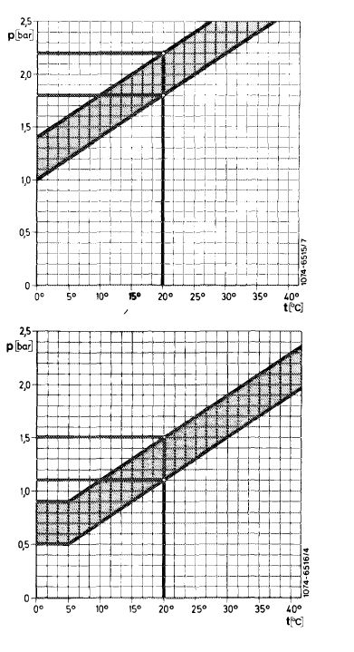
(T) starting 1981 (usa) 1980/81
Warm-up compensator Bosch end no. 067
|
 |
|||
|
Example:
Ambient temperature 20 °C = control pressure 1.4—1.8 bar gauge pressure.
Stabilizing time at + 20 °C = 2-4 minutes.
|
||||
|
(aus) (T) starting 1981
|
||||
|
Warm-up compensator Bosch end no. 057
|
||||
|
Example:
Ambient temperature 20 °C = control pressure 1.1 —1.5 bar gauge pressure.
Stabilizing time at + 20 °C = 2-4 minutes.
|
||||
|
5 Check stabilizing time of warm-up compensator. Read initial control pressure at + 20 °C. The stabilizing time at 3.4 bar gauge pressure should be within tolerance. Additional electric consumers switched off, minimum voltage 12 Volts.
|
||||
|
|
||||
|
Checking system pressure at idle with engine cold or at operating temperature
|
||||
|
|
||||
|
6 Close valve screw on pressure measuring device. When measuring pressure, with 2 valve screws, close valve screw at connection 3.
7 The system pressure should amount to 5.0—5.6 bar gauge pressure.
8 If the system pressure of 5.0—5.6 bar gauge pressure is not attained or exceeded, perform the following checkups:
a) Check delivery capacity of fuel pump (07.3—130).
b) Recondition system pressure regulator (07.3—210).
c) Check fuel return flow line for passage.
9 Re-open valve screw.
|
||||
|
|
||||
|
07.3.2 lla-120/15
|
F 2
|
|||
|
|
||||
|
|
|||
|
Checking control pressure at idle with engine at operating temperature
|
|||
|
|
|||
|
10 Open both valve screws or valve screw on pressure measuring device.
11 Control pressure should increase to specified value (warm-up compensator stabilized).
If the control pressure is not attained, perform the following checkups:
a) Check intake manifold vacuum. For this purpose, pull off vacuum hose (arrow) on warm-up compensator and attach a T-fitting for pressure gauge.
Read intake manifold vacuum and transfer to vacuum diagram.
|
|||
|
|
|||
|
(@) Federal 1977-1979 (aus) (V) starting 1977
|
 |
||
|
Example:
Intake manifold vacuum 400 mbar = control pressure 3.5—3.9 bar gauge pressure.
|
|||
|
(usa) Federal high altitudes 1977
|
|||
|
Example:
Intake manifold vacuum 400 mbar = control pressure 3.7—4.1 bar gauge pressure.
|
|||
|
GO 1977-1980
(©) California 1977-1979
|
|||
|
Example.
Intake manifold vacuum 400 mbar = control pressure 3.1—3.5 bar gauge pressure.
|
|||
|
07.3.2 I la—1 20/16 F2
|
|||
|
|
|||
|
|
||||
|
Note: Starting model year (7) 1981, <@) 1980 the vacuum flow is straight. Control pressure is therefore independent of intake manifold vacuum.
b) Test voltage on warm-up compensator with engine running. Pull electrical connection from warm-up compensator and test for voltage. Minimum voltage 12 Volts (without electrical consumers).
|
||||
|
|
||||
|
c) Test heater coil with an ohmmeter for passage. Resistance: 20—40 ft.
Replace warm-up compensator.
d) If control pressure is above nominal value, recondition system pressure regulator (07.3—210).
|
 |
|||
|
Mixture controller with safety switch
1 Fuel pump
2 Safety switch — air flow sensor plate
3 Warm-up compensator
4 Fuel pump
a Terminal 50 (starting) b Terminal 1 5/54 (ignition) c Plug connection 14-point tail lamp unit harness
|
||||
|
|
||||
|
Mixture controller without safety switch
|
 |
|||
|
Up to model year 1 981
1 Fuel pump relay
2 Warm-up compensator a To fuel pump
|
||||
|
|
||||
|
Starting model year 1981 1 Fuel pump relay 3 Warm-up compensator c To fuel pump
|
 |
|||
|
|
||||
|
07.3.2 lla—120/1 7
|
F 2
|
|||
|
|
||||
|
|
||||
|
12 Check full load enrichment. For this purpose, pull vacuum hose (arrow) from warm-up compensator, control pressure should now drop to specified value.
If the control pressure is not attained, replace warm-up compensator.
|
 |
|||
|
|
||||
|
13 Check acceleration enrichment.
|
 |
|||
|
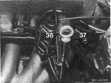
(7) starting 1981, @) 1980/81
Check thermovalve (37) 50 °C for passage. For this purpose, pull off vacuum hoses (a and b). The thermovalve is closed below approx. 50 °C coolant temperature, above approx. 50 °C coolant temperature there should be passage, if not, replace thermovalve (37).
|
||||
|
|
||||
 |
||||
|
|
||||
|
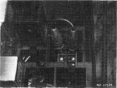
Stop engine, pull off fuel pump relay (arrow).
|
 |
|||
|
|
||||
|
07.3.2 I la—1 20/18
|
F 2
|
|||
|
|
||||
|
|
||||
|
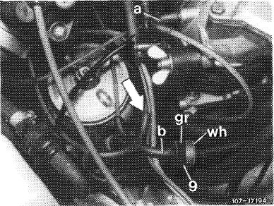
Pull vacuum line from distributor (arrow).
|
 |
|||
|
|
||||
|
Plug vacuum pump to vacuum line toward warm-up compensator and activate warm-up compensator with 0.5 bar vacuum.
|
 |
|||
|
|
||||
|
Bridge the two jacks on fuel pump relay coupler.
Up to model year 1981: Jacks 1 and 2. Starting model year 1982: Jacks 7 and 8.
|
 |
|||
|
|
||||
|
The control pressure should then amount to 1.4—1.8 bar gauge pressure. If the control pressure deviates from nominal value, replace warm-up compensator.
|
,.*
¥
|
|||
|
|
||||
|
07.3.2 lla-120/19
|
F 2
|
|||
|
|
||||
|
|
|||
|
Checking fuel distributor and fuel pump for leaks
14 Stop engine. Control pressure will then drop below opening pressure on injection valves (approx. 2.8 bar gauge pressure).
15 If the control pressure drops inmediately to 0 bar gauge pressure, replace check valve on fuel pump or subsequently install.
16 If the pressure drops slowly, unscrew fuel return line on fuel distributor. Fuel will emerge in the event of a leak on regulator piston or pressure compensating valve. If there is more than 1 drop in 5 seconds, recondition system pressure regulator or pressure compensating valve (07.3—210).
17 Check fuel reservoir for leaks (not included in time rate). For this purpose, disconnect leak line between fuel reservoir and intake damper.
18 Loosen leak line on intake damper and pull off. Loosen clamp, pressureless leaking is permissible. Replace fuel reservoir, if required (07.3—270).
|
|||
|
|
|||
|
19 Check cold-starting valve (98) for leaks. For this purpose, remove cold-starting valve (07.3—125, section „Checking for leaks”).
20 Close pressure measuring device, while catching fuel with a rag.
21 Connect fuel lines, run engine once again and check fuel connections for leaks.
|
 |
||
|
|
|||
|
07.3.2 I la—1 20/20 F2
|
|||
|
|
|||