Checking and regulating engine
|
|
||||||||||||||||||||||||||||||||||||||||||
|
07.3—110 Checking and regulating engine
|
||||||||||||||||||||||||||||||||||||||||||
|
|
||||||||||||||||||||||||||||||||||||||||||
|
A. Standard version
|
||||||||||||||||||||||||||||||||||||||||||
|
|
||||||||||||||||||||||||||||||||||||||||||
|
Testing and adjusting values
|
||||||||||||||||||||||||||||||||||||||||||
|
|
||||||||||||||||||||||||||||||||||||||||||
|
Engine
|
Idle speed 1/min
|
Idle speed emission value % CO
|
||||||||||||||||||||||||||||||||||||||||
|
|
||||||||||||||||||||||||||||||||||||||||||
|
110.984/985/986/987
|
750-850
|
|||||||||||||||||||||||||||||||||||||||||
|
|
||||||||||||||||||||||||||||||||||||||||||
|
0.5-1.5
|
||||||||||||||||||||||||||||||||||||||||||
|
|
||||||||||||||||||||||||||||||||||||||||||
|
110.988/989/990
|
700-800
|
|||||||||||||||||||||||||||||||||||||||||
|
|
||||||||||||||||||||||||||||||||||||||||||
|
||||||||||||||||||||||||||||||||||||||||||
|
|
||||||||||||||||||||||||||||||||||||||||||
|
Voltages at ignition coil (with engine stopped and ignition switched on) Transistorized ignition system TSZ 4
|
||||||||||||||||||||||||||||||||||||||||||
|
|
||||||||||||||||||||||||||||||||||||||||||
|
||||||||||||||||||||||||||||||||||||||||||
|
|
||||||||||||||||||||||||||||||||||||||||||
|
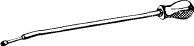
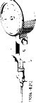
Screw driver 3 mm with tommy handle for readjusting idle speed emission value
|
 |
000 589 14 11 00
|
||||||||||||||||||||||||||||||||||||||||
|
|
||||||||||||||||||||||||||||||||||||||||||
|
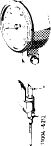
Puller
|
123 589 05 33 00
|
|||||||||||||||||||||||||||||||||||||||||
|
|
||||||||||||||||||||||||||||||||||||||||||
|
11OO4-B204
|
||||||||||||||||||||||||||||||||||||||||||
|
|
||||||||||||||||||||||||||||||||||||||||||
|
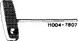
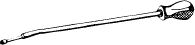
Installer
|
11004-8278
|
123 589 00 15 00
|
||||||||||||||||||||||||||||||||||||||||
|
|
||||||||||||||||||||||||||||||||||||||||||
|
07.3.2 Ha—110/1 F2
|
||||||||||||||||||||||||||||||||||||||||||
|
|
||||||||||||||||||||||||||||||||||||||||||
|
|
||
|
Oil telethermometer J- 116 589 27 2100
 |
||
|
|
||
|
Conventional testing instruments and accessories
|
||
|
|
||
|
CO-measuring instrument, revolution counter, stroboscope, voltmeter, oscilloscope
Digital tester e.g. made by Bosch, MOT 001.03
|
||
|
|
||
|
Note
|
||
|
|
||
|
Do not regulate engine of it is too hot, e.g. immediately following a fast drive or after measuring output on chassis dynamometer.
|
||
|
|
||
|
Regulation
|
||
|
|
||
|
1 Switch-off air conditioning or automatic climate control. Move selector lever into position „P”.
2 Remove air cleaner.
|
||
|
|
||
|
3 Check engine regulating linkage for easy operation and wear. Lubricate all bearing points and ball sockets.
4 Perform full throttle checkup from inside vehicle (30-300).
5 Connect test instruments: CO-measuring instrument, revolution counter, stroboscope, oscilloscope, digital tester, oil telethermometer.
6 Evaluate oscilloscope display.
|
||
|
|
||
|
07.3.2 I la—110/2 F2
|
||
|
|
||
|
|
|||
|
7 Check firing point and adjust, if required. Check centrifugal and vacuum ignition adjustment (15—501).
8 Test battery voltages.
Note: Voltmeter connection remains unchanged during tests a) and b).
|
|||
|
|
|||
|
a) Rest potential
Connect voltmeter to battery while paying attention to polarity and read voltages. Nominal value 12.2 Volts.
|
|||
|
|
|||
|
b) Starting voltage
Pull plug from transmitter of ignition distributor on switching unit (green cable) or protective plug, part no. 102 589 02 21 00, plug on diagnosis socket.
Operate starter for a short moment while reading voltage. Nominal value min. 10 Volts; if nominal value is not attained, test battery, charge or replace, if required.
|
 |
||
|
|
|||
|
9 Voltages on ignition coil:
|
|||
|
|
|||
|
Transistorized ignition system TSZ 4
Test voltage on terminal 15 of ignition coil. For this purpose, disconnect positive cable of voltmeter from battery and connect to terminal 15 of ignition coil.
Switch-on ignition and read voltage. Nominal value approx. 4.5 volts.
|
|||
|
|
|||
|
Voltage test on terminal 1 of ignition coil. For this purpose, disconnect positive cable of voltmeter from terminal 15 and connect to terminal 1 of ignition coil.
Switch-on ignition and read voltage. Nominal value 0.5-2.0 Volts.
Test pre-resistance bridge by starting engine and reading voltage during starting procedure. Nominal value 10 Volts.
|
|||
|
|
|||
|
07.3.2 lla-110/3 F2
|
|||
|
|
|||
|
|
||||
 |
||||
|
|
||||
|
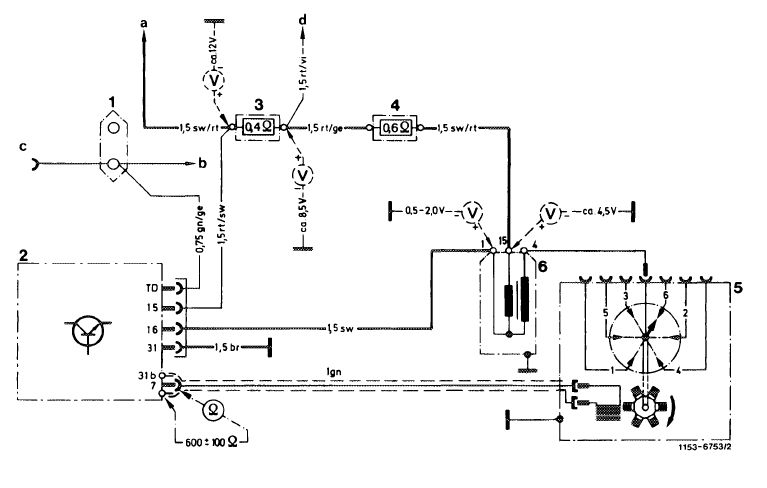
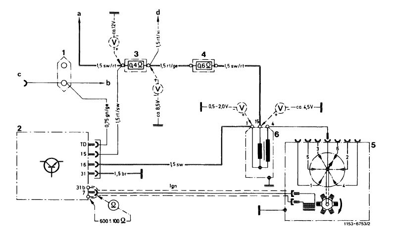
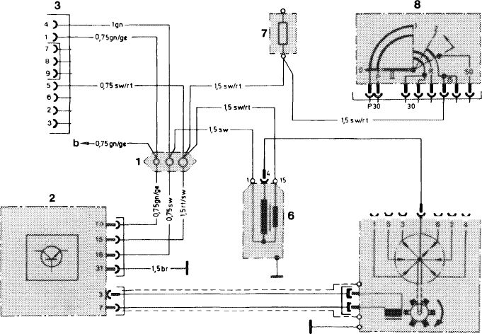
Wiring diagram breakerless transistorized ignition TSZ 4
|
||||
|
|
||||
|
1 2-point cable connector
2 Switching unit
3 Pre-resistor 0.4 £1
4 Pre-resistor 0.6 £2
5 Ignition distributor with transmitter section
6 Ignition coil
|
a Ignition starting switch b Instrument cluster revolution counter c Diagnosis socket d Terminal 16 starter
|
Color code br = brown ge = yellow gn = green rt = red sw = black
|
||
|
|
||||
|
Transistorized ignition system TSZ 8 u
Switch-on ignition with engine stopped. Check voltage on jack 5 of diagnosis socket (3). Test terminal 15 against ground.
Nominal value: Battery voltage.
Test voltage difference between terminal 15 and terminal 1 on jack 5 and 4 of diagnosis socket (3).
Nominal value: 0 Volt.
|
||||
|
|
||||
|
If nominal values are not attained, test ignition system (15-562).
07.3.2 lla-11074 F2
|
||||
|
|
||||
|
|
||||||||||||||||||||||||||||||||||||||||||||
 |
||||||||||||||||||||||||||||||||||||||||||||
|
|
||||||||||||||||||||||||||||||||||||||||||||
|
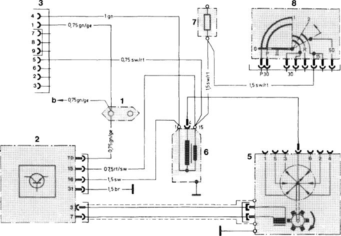
Wiring diagram breakerless transistorized ignition without pre-resistors TSZ 8 u in model 123
|
||||||||||||||||||||||||||||||||||||||||||||
|
|
||||||||||||||||||||||||||||||||||||||||||||
|
1 Line connector
2 Switching unit
3 Diagnosis socket
5 Ignition distributor
6 Ignition coil
7 Fuse box terminal 15
8 Ignition starting switch
|
a To fuse box, input terminal 1 5
b To fuel pump relay with rpm limitation
|
Color code br = brown ge = yellow gn = green rt = red sw = black
|
||||||||||||||||||||||||||||||||||||||||||
|
|
||||||||||||||||||||||||||||||||||||||||||||
 |
||||||||||||||||||||||||||||||||||||||||||||
|
Wiring diagram breakerless transistorized ignition without pre-resistors TSZ 8 u in model 107, 126
1 Line connector a To fuse box, input terminal 1 5
2 Switching unit b To fuel pump relay with rpm limitation
3 Diagnosis socket
5 Ignition distributor
6 Ignition coil
7 Fuse box terminal 15
|
|
|||||||||||||||||||||||||||||||||||||||||||
|
|
||||||||||||||||||||||||||||||||||||||||||||
|
8 Ignition starting switch
|
||||||||||||||||||||||||||||||||||||||||||||
|
|
||||||||||||||||||||||||||||||||||||||||||||
|
07.3.2 I la—110/5 F2
|
||||||||||||||||||||||||||||||||||||||||||||
|
|
||||||||||||||||||||||||||||||||||||||||||||
|
|
|||
|
10 Check intake system for leaks. For this purpose, spray all sealing points with Iso-Oktan DIN 51756 or benzine.
Attention!
Do not use conventional fuel for spraying (unhealthy vapors). Pay attention to inflammability and do not spray on red-hot parts or components of ignition system.
|
|||
|
|
|||
|
Checking decel shutoff :
|
 |
||
|
Checking on chassis dynamometer
Run on chassis dynamometer at approx. 70 km/h in 4th speed or driving position „D”. Release accelerator pedal, air flow sensor plate will then move into zero position. When combustion starts again at approx. 1100 /min or approx. 1300/min with refrigerant compressor, the air flow sensor plate will move into idle speed position. Check decel shutoff valve and its activation, if required (07.3—140).
|
|||
|
|
|||
|
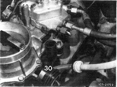
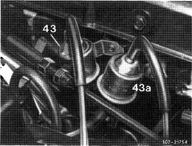
Checking without chassis dynamometer (07.3—140).
Run engine at idle.
Pull vacuum lines from switchover valve (43a) and connect with each other. Decel shutoff valve (30) opens, engine should now stop. Check activation, if required.
|
 |
||
|
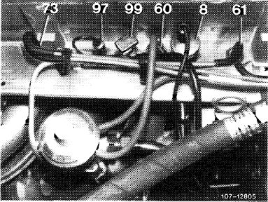
43 Switchover valve air conditioning (identification: green cap)
43a Switchover valve decel shutoff (identification: gray cap)
|
|||
|
|
|||
|
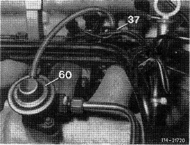
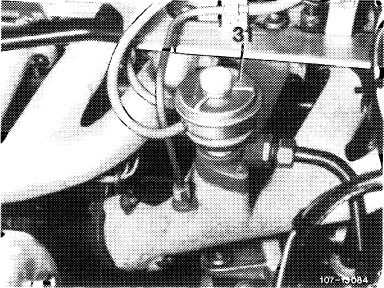
12 Check EGR.
Pull vacuum line from EGR valve (60), plug-on test hose and activate with a vacuum. If engine is not clearly running worse, replace EGR valve. Check activation, if required (14—475).
13 Run engine to 75—85 °C oil temperature.
|
 |
||
|
|
|||
|
07.3.2 lla-110/6 F2
|
|||
|
|
|||
|
|
|||
|
14 Vehicles with cruise control/tempomat:
|
 |
||
|
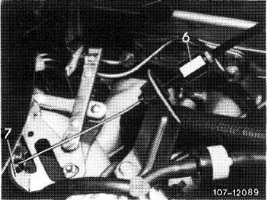
Cruise control/tempomat, pneumatic
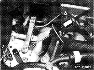
Check whether bowden wire for cruise control/tempomat rests free of tension against regulating lever (7). Adjust with adjusting nut (6), if required.
|
|||
|
|
|||
|
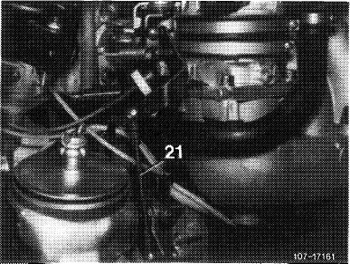
Cruise control/tempomat, electrical
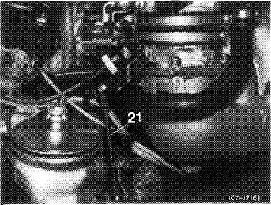
Check whether actuator rests against idle stop of cruise control/tempomat. For this purpose, disconnect pull rod (21) and push lever of actuator clockwise against idle speed stop.
When connecting pull rod (21), make sure that the lever of the actuator is raised by approx. 1 mm from idle speed stop. Adjust pull rod, if required.
|
 |
||
|
|
|||
|
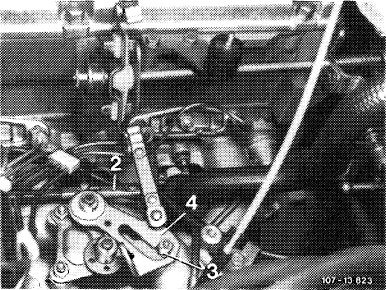
15 Check whether throttle valve rests against idle speed stop. Disconnect connecting rod for this purpose.
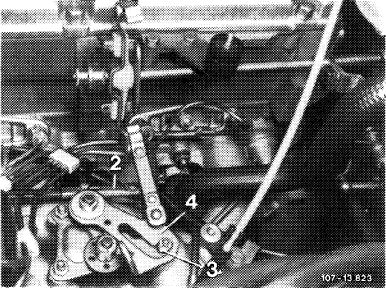
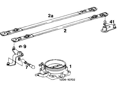
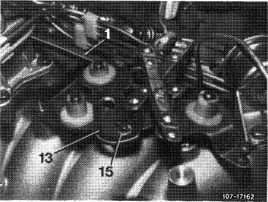
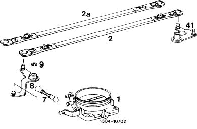
16 Check whether roller (3 and 15) on slotted lever (4 and 13) rests free of tension against final stop. Adjust with connecting rod (1 and 2), if required.
|
 |
||
|
Model 123
|
|||
|
|
|||
|
Model 126
|
|||
|
|
|||
|
07.3.2 tla—110/7 F2
|
|||
|
|
|||
|
|
|||
|
The connecting rod can now be adjusted on one side only. Pay attention to installation position (refer to Fig.).
|
 |
||
|
2 Former version 2a Present version
|
|||
|
|
|||
|
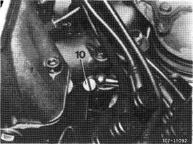
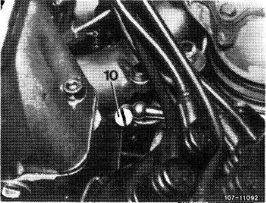
17 Set to specified engine speed by means of idle speed air screw (10).
|
 |
||
|
|
|||
|
18 Adjust idle speed emission value:
|
 |
||
|
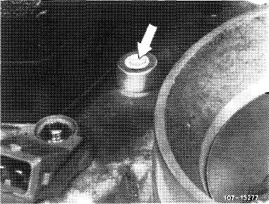
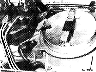
With gray iron fuel distributor
For this purpose, unscrew closing plug (arrow).
Attention!
On vehicles manufactured after 1.10.1976, remove safety plug first.
|
|||
|
|
|||
|
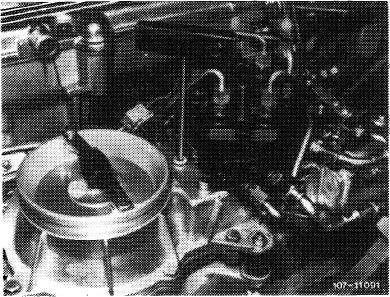
Insert screw driver through bore against idle speed mixture control screw and adjust emission value by turning screw.
Turning counterclockwise = leaner Turning clockwise = richer
Close bore for closing plug. Accelerate for a short moment, check idle speed emission value and readjust, if required.
|
 |
||
|
|
|||
|
07.3.2 I la—110/8 F2
|
|||
|
|
|||
|
|
|||
|
Following adjustment, install a blue safety plug (arrow), part no. 000 997 59 86 on vehicles manufactured after 1.10.1976.
|
 |
||
|
|
|||
|
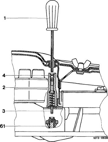
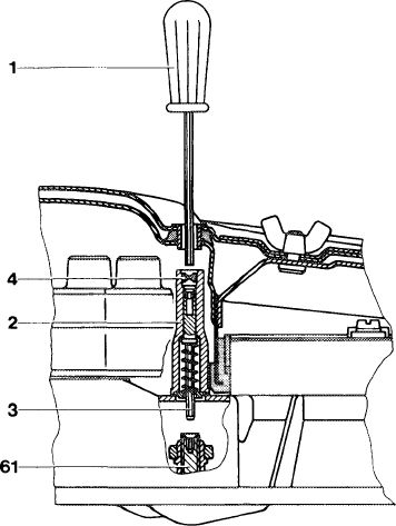
With light alloy fuel distributor
Pull out safety plug (4) by means of puller.
Push with screw driver (1) against adjusting device (2). Push adjusting device down with screw driver against force of spring, turn slightly until hexagon (3) enters mixture control screw (61).
Turning counterclockwise = leaner Turning clockwise = richer
Release screw driver, the compression spring will disengage adjusting device from mixture control screw.
|
 |
||
|
1 Screw driver
2 Adjusting device
3 Hexagon
4 Safety plug
61 Mixture control screw
|
|||
|
|
|||
|
Accelerate for a short moment, check idle speed emission value and readjust, if required.
Following adjustment, install a blue safety plug (4), part no. 000 997 56 86 by means of installer.
|
|||
|
|
|||
|
07.3.2 I la—110/9 F2
|
|||
|
|
|||
|
|
|||
|
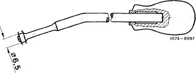
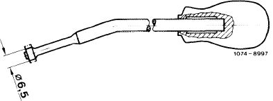
Note: The diameter of the installer for knocking back safety plug for protective cap of mixture control screw (61) had to be changed from 8 mm to 6.5 mm.
In spare parts sector only installers with changed diameter are now available. On former installers, grind diameter down to 6.5 mm.
|
 |
||
|
|
|||
|
19 Mount air cleaner. Check idle speed and idle speed emission value once again and readjust, if required.
20 Move selector lever into driving position, engage air conditioning, turn power steering to full lock, engine should run smoothly. Readjust engine speed, if required.
|
|||
|
|
|||
|
07.3.2 Ma—110/10 F2
|
|||
|
|
|||
|
|
||||||||||||||||||||||||
|
Identification: Label in national language on radiator cross member. Adjust engines according to data of respective emission label.
|
||||||||||||||||||||||||
|
|
||||||||||||||||||||||||
|
Testing and adjusting values
|
||||||||||||||||||||||||
|
|
||||||||||||||||||||||||
|
National version
and
model year
|
Idle speed 1/min
|
Idle speed emission value % CO without air injection
|
||||||||||||||||||||||
|
|
||||||||||||||||||||||||
|
Label: Color code silver.
|
||||||||||||||||||||||||
|
|
||||||||||||||||||||||||
|
1977-1980
|
800
|
0.5-1.5
|
||||||||||||||||||||||
|
|
||||||||||||||||||||||||
|
1981/82
|
750-850
|
0.3-1.3
|
||||||||||||||||||||||
|
|
||||||||||||||||||||||||
|
Label: In Japanese language.
|
||||||||||||||||||||||||
|
|
||||||||||||||||||||||||
|
1977-1980
|
800
|
0.4-2.0
|
||||||||||||||||||||||
|
|
||||||||||||||||||||||||
|
Label: Color code blue.
|
||||||||||||||||||||||||
|
|
||||||||||||||||||||||||
|
1977-1980
|
800
|
0.5-1.5
|
||||||||||||||||||||||
|
|
||||||||||||||||||||||||
|
1981/82
|
750-850
|
0.3-1.3
|
||||||||||||||||||||||
|
|
||||||||||||||||||||||||
|
Label: Color code Federal black, California yellow.
|
||||||||||||||||||||||||
|
|
||||||||||||||||||||||||
|
1977-1979
|
800
|
0.4-2.0
|
||||||||||||||||||||||
|
|
||||||||||||||||||||||||
|
Battery voltages
|
||||||||||||||||||||||||
|
|
||||||||||||||||||||||||
|
Rest potential
|
12.2 V
|
|||||||||||||||||||||||
|
|
||||||||||||||||||||||||
|
Starting voltage min.
|
10 V
|
|||||||||||||||||||||||
|
|
||||||||||||||||||||||||
|
Voltages on ignition coil (with engine stopped and ignition switched on)
|
||||||||||||||||||||||||
|
|
||||||||||||||||||||||||
|
Transistorized ignition system TSZ 4
|
||||||||||||||||||||||||
|
|
||||||||||||||||||||||||
|
||||||||||||||||||||||||
|
|
||||||||||||||||||||||||
|
07.3.2 Ma—110/11 F2
|
||||||||||||||||||||||||
|
|
||||||||||||||||||||||||
|
|
|||||
|
Transistorized ignition system TSZ 8 u
|
|||||
|
|
|||||
|
Terminal 15 (bushing on diagnosis socket) against ground
|
Battery voltage
|
||||
|
|
|||||
|
Terminal 1 and 15 (bushing 5 and 4 on diagnosis socket)
|
0 V
|
||||
|
|
|||||
|
Special tools
|
|||||
|
|
|||||
|
Screw driver 3 mm with tommy handle for readjusting idle speed emission value
|
 |
000 589 14 11 00
|
|||
|
|
|||||
|
Puller
|
123 589 05 33 00
|
||||
|
|
|||||
|
Installer
|
11004-8278
|
123 589 00 15 00
|
|||
|
|
|||||
|
Oil telethermometer
|
 |
116 589 27 21 00
|
|||
|
|
|||||
|
Conventional testing instruments and accessories
|
|||||
|
|
|||||
|
CO-measuring instrument, revolution counter, stroboscope, oscilloscope, voltmeter
|
|||||
|
|
|||||
|
Digital tester
|
e.g. made by Bosch, MOT 001.03
|
||||
|
|
|||||
|
Note
|
|||||
|
|
|||||
|
Do not regulate engine when engine is too hot, e.g. immediately after a fast drive or after measuring output on chassis dynamometer.
|
|||||
|
|
|||||
|
Regulation
|
|||||
|
|
|||||
|
1 Switch-off air conditioning or automatic climate control. Move selector lever into position „P”
2 Remove air cleaner.
|
|||||
|
|
|||||
|
07.3.2 I la—110/12 F2
|
|||||
|
|
|||||
|
|
|||
|
3 Check engine regulating linkage for easy operation and wear. Lubricate all bearing points and ball sockets.
4 Perform full throttle checkup from inside vehicle (30-300).
5 Connect test instruments: CO-measuring instrument, revolution counter, stroboscope, oscilloscope, digital tester, oil telethermometer.
6 Evaluate oscilloscope display.
|
|||
|
|
|||
|
7 Check firing point and adjust, if required. Check centrifugal and vacuum ignition adjustment (15—501).
8 Test battery voltages.
Note: Voltmeter connection remains unchanged during tests a) and b).
|
|||
|
|
|||
|
a) Rest potential
Connect voltmeter to battery while paying attention to polarity and read voltages. Nominal value 12.2 Volts.
|
|||
|
|
|||
|
b) Starting voltage
Pull plug from transmitter of ignition distributor on switching unit (green cable) or plug protective plug, part no. 102 589 02 21 00 on diagnosis socket.
Operate starter for a short moment while reading voltage. Nominal value min. 10 Volts. If nominal value is not attained, test battery, charge and renew, if required.
|
 |
||
|
|
|||
|
9 Voltages on ignition coil:
|
|||
|
|
|||
|
Transistorized ignition system TSZ 4
Test voltage on terminal 15 of ignition coil. For this purpose, disconnect voltmeter from battery and connect to terminal 15 of ignition coil.
Switch-on ignition and read voltage. Nominal value approx. 4.5 Volts.
|
|||
|
|
|||
|
07.3.2 Ma —110/13 F2
|
|||
|
|
|||
|
|
||||
|
Test voltage on terminal 1 of ignition coil. For this purpose, disconnect positive cable of voltmeter from terminal 15 and connect to terminal 1 of ignition coil.
Switch-on ignition and read voltage. Nominal value 0.5-2.0 Volts.
Test pre-resistance bridge by starting engine and read voltage during starting procedure. Nominal value 10 Volts.
|
||||
|
|
||||
 |
||||
|
|
||||
|
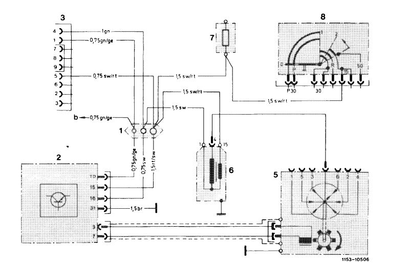
Wiring diagram breakerless transistorized ignition system TSZ 4
|
||||
|
|
||||
|
1 2-point cable connector
2 Switching unit
3 Pre-resistor 0.4 £1
4 Pre-resistor 0.6 £2
5 Ignition distributor with transmitter section
6 Ignition coil
|
a Ignition starting switch b Instrument cluster revolution counter c Diagnosis socket d Terminal 16 starter
|
Color code br = brown ge = yellow gn = green rt = red sw = black
|
||
|
|
||||
|
07.3.2 I la—110/14 F2
|
||||
|
|
||||
|
|
||||
|
Transistorized ignition system TSZ 8 u
Switch-on ignition with engine stopped. On jack 5 of diagnosis socket (3) test voltage, terminal 15 against ground.
Nominal value: Battery voltage.
On jack 4 and 5 of diagnosis socket (3) test voltage difference between terminal 15 and terminal 1.
Nominal value: 0 Volt.
If nominal voltages are not attained, test ignition system (15-562).
|
||||
|
|
||||
|
5 ^^^^^”*^P ^ „^^^” ■ ■ ■ ■ ^^^^ ^ ^^ ^^v^^v^^^^^ ^ ^^V^nnp^^^Fmvwt
|
||||
|
|
||||
|
1153-10506
|
||||
|
|
||||
|
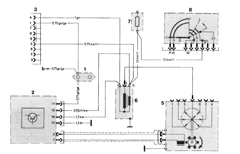
Wiring diagram breakerless transistorized ignition without pre-resistors TSZ 8 u in model 123
|
||||
|
|
||||
|
1 Line connector
2 Switching unit
3 Diagnosis plug
5 Ignition distributor
6 Ignition coil
7 Fuse box terminal 15
8 Ignition starting switch
|
a To fuse box, input
terminal 15 b To fuel pump relay
with rpm limitation
|
Color code br = brown ge = yellow gn = green rt = red sw = black
|
||
|
|
||||
|
07.3.2 lla-110/15 F2
|
||||
|
|
||||
|
|
||||
 |
||||
|
|
||||
|
1153-10505
|
||||
|
|
||||
|
Wiring diagram breakerless transistorized ignition without pre-resistors TSZ 8 u in model 107, 126
|
||||
|
|
||||
|
1 Line connector
2 Switching unit
3 Diagnosis socket
5 Ignition distributor
6 Ignition coil
7 Fuse box terminal 15
8 Ignition starting switch
|
a To fuse box, input
terminal 1 5 b To fuel pump relay
with rpm limitation
|
Color code br = brown ge = yellow gn = green rt = red sw = black
|
||
|
|
||||
|
10 Check intake system for leaks. For this purpose, spray all sealing points with Iso-Oktan DIN 51756 or benzine.
Attention!
Do not use conventional fuel for spraying (unhealthy vapors), pay attention to inflammability and do not spray on red-hot parts or components of ignition system.
|
||||
|
|
||||
|
07.3.2 lla-110/16 F2
|
||||
|
|
||||
|
|
|||||
|
11 Check EGR.
Pull red/purple vacuum line from EGR valve (31). Plug-on test hose and activate with a vacuum. If the engine is not running noticeably worse, replace EGR valve.
12 Run engine to 75—85 °C oil temperature.
|
 |
||||
|
|
|||||
|
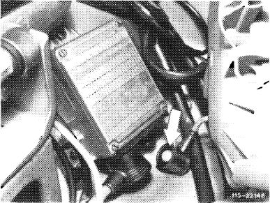
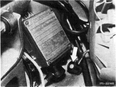
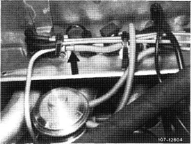
13 Connect CO-measuring instrument.
For this purpose, pull connecting hose (arrow) of measuring point (exhaust back pressure line) on
|
 |
||||
|
C)
|
and
|
(@) version.
|
|||
|
|
|||||
|
Respective model years: CD 1977-1980 (@) 1977-1979
Connect CO-measuring instrument and exhaust backpressure line by means of a hose.
No catalyst is installed on (usa) tourist vehicles, for this reason, the exhaust gas value can be measured on exhaust tail pipe.
14 Vehicles with cruise control/tempomat:
|
|||||
 |
|||||
|
Cruise control/tempomat, pneumatic
Check whether bowden wire for cruise control/tempomat rests free of tension against regulating lever (7). Adjust with adjusting screw (6), if required.
|
|||||
|
|
|||||
|
Cruise control/tempomat, electric
Check whether activator rests against idle speed stop of cruise control/tempomat. For this purpose, disconnect pull rod (21) and push lever of activator clockwise against idle speed stop.
When connecting pull rod (21), make sure that lever of activator is raised by approx. 1 mm from idle speed stop. Adjust pull rod, if required.
|
 |
||||
|
|
|||||
|
07.3.2 lla-110/17 F2
|
|||||
|
|
|||||
|
|
|||
|
15 Check whether throttle valve rests against idle speed stop. Disconnect connecting rod for this purpose.
16 Check whether roller (3 and 15) in slotted lever (4 and 13) rests free of play against final stop. Adjust by means of connecting rod (1 and 2), if required.
|
 |
||
|
Model 123
|
|||
|
|
|||
|
Model 1 26
|
 |
||
|
|
|||
|
Connecting rod can now be adjusted on one side only. Pay attention to installation position (refer to Fig.).
|
 |
||
|
2 Former version 2a Present version
|
|||
|
|
|||
|
1 7 Adjust to specified engine speed by means of idle speed air screw (10).
|
 |
||
|
|
|||
|
07.3.2 Ma—110/18 F2
|
|||
|
|
|||
|
|
|||
|
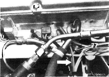
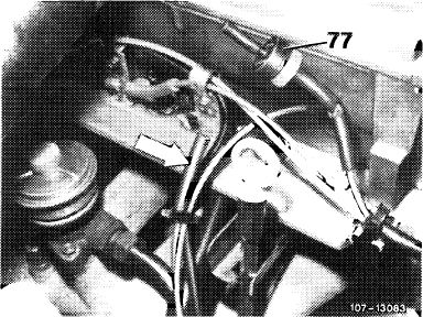
18 Check idle speed emission value:
(aus) 1977-1982 (T) 1977-1982
Check idle speed emission value without injecting air. For this purpose, pull blue/purple vacuum line (arrow) from delay valve (77) and close small tube. The air injection is now disconnected.
|
 |
||
|
|
|||
 |
|||
|
|
|||
|
i±) 1977-1980 (usa) 1977-1979
Check idle speed emission value without air injection in cylinder head. For this purpose, pull blue vacuum line from blue thermovalve (60) and close line. The air injection is now disconnected.
|
 |
||
|
|
|||
|
19 Adjust idle speed emission value:
|
 |
||
|
With gray iron fuel distributor
|
|||
|
Unscrew closing plug (arrow) for this purpose.
|
|||
|
|
|||
|
07.3.2 I la—110/19 F2
|
|||
|
|
|||
|
|
||||
|
Insert screw driver through bore against idle speed mixture control screw and set emission value by turning screw.
Turning counterclockwise = leaner Turning clockwise = richer
Close bore for closing plug. Accelerate for a short moment, check idle speed emission value once again and readjust, if required.
Put back vacuum line on thermovalve.
Check idle speed emission value once again (air injection operational). The idle speed emission value should be below previously set value.
|
 |
|||
|
|
||||
|
With light alloy fuel distributor
Pull out fuse plug (4) with puller.
Push with screw driver (1) against adjusting device (2). Push adjusting device down with screw driver against force of spring, turn slightly until hexagon (3) enters mixture control screw (61).
Turning counterclockwise = leaner Turning clockwise = richer
Release screw driver, the coil spring will push adjusting device automatically out of mixture control screw.
|
 |
1073-8838
|
||
|
1 Screw driver
2 Adjusting device
3 Hexagon
4 Safety plug
61 Mixture control screw
|
||||
|
|
||||
|
07.3.2 Ha—110/20 F2
|
||||
|
|
||||
|
|
|||
|
Accelerate for a short moment, check idle speed emission value and readjust, if required.
Following adjustment, install a blue safety plug (4), part no. 000 997 56 86 by means of installer.
|
|||
|
|
|||
|
Note: The diameter of the installer for knocking-in safety plug for protective cap of mixture control screw (61) has been changed from 8 mm to 6.5 mm.
In spare parts sector only installers with reduced diameter are now available. On former installers, grind diameter down to 6.5 mm.
|
 |
||
|
|
|||
|
20 Mount air cleaner. Check idle speed and idle speed emission value once again and readjust, if required.
21 Place selector lever into driving position, engage air conditioning, turn power steering to full lock, engine should be running smoothly. Readjust engine speed, if required.
|
|||
|
|
|||
|
07.3.2 lla-110/21 F2
|
|||
|
|
|||