Checking float chamber external venting system
|
|
||||
|
07.2—182 Checking float chamber external venting system
|
||||
|
|
||||
|
Special tool
|
||||
|
|
||||
|
Clamp
|
 |
000 589 40 37 00
|
||
|
|
||||
|
Conventional tool
|
||||
|
|
||||
|
Vacuum tester
|
||||
|
|
||||
|
Note
|
||||
|
|
||||
|
The float chamber external venting system influences hot start characteristics, fuel consumption, bypass characteristics stage I and II and driving performance under full load. If the float chamber external venting system is defective, the fuel level in float chamber will be exposed to atmospheric air pressure, the fuel in mixing tubes will rise to an inadmissible level and the engine will be supplied with excessively rich fuel. High fuel consumption and driving faults will result.
|
||||
|
|
||||
|
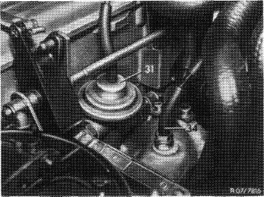
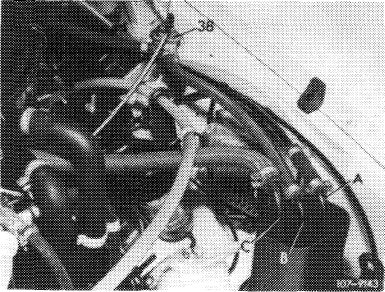
A. ©1974 California
|
||||
|
|
||||
|
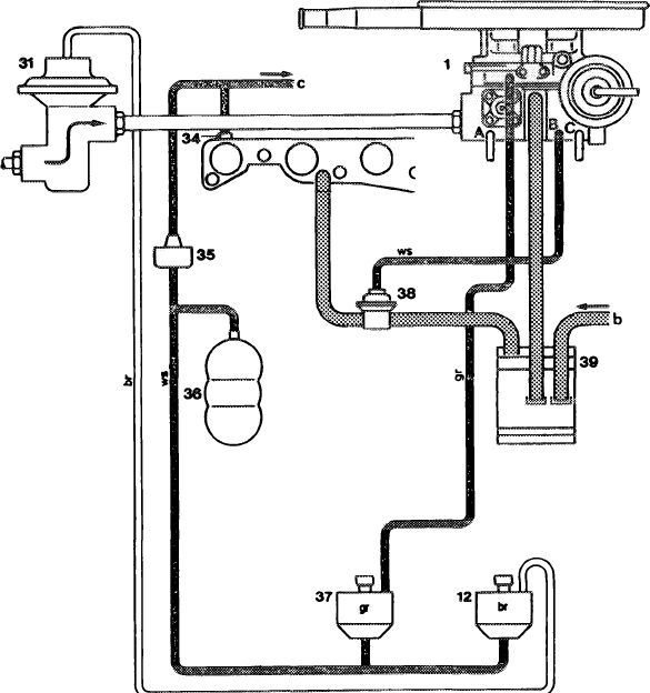
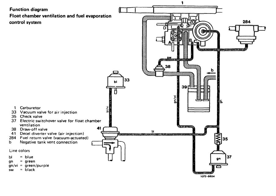
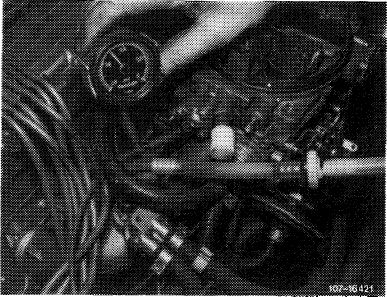
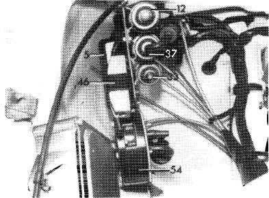
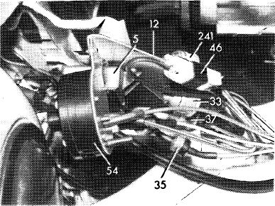
Function diagram
Float chamber ventilation and fuel
evaporation control system
|
 |
|||
|
1 Carburetor
12 Electric switchover valve for EGR
31 EGR valve
34 Vacuum connection on intake pipe
35 Check valve
36 Vacuum supply tank
37 Electric switchover valve for float chamber ventilation
38 Draw-off valve
39 Charcoal canister
b Negative tank vent connection c Air conditioner connection A Vacuum switch connection (EGR) B Draw-off valve connection C Decel diverter valve connection, fuel return valve, ignition switchover and vacuum governor
Line color
br = brown gr = grey ws = white
|
||||
|
|
||||
|
TO73-8853
|
||||
|
|
||||
|
07.2.2 la—182/1
|
||||
|
|
||||
|
|
||||
|
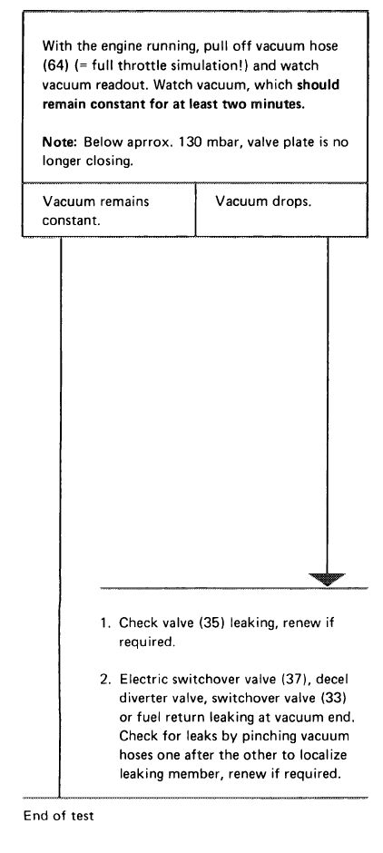
Test conditions:
|
All electric fuses in order. Engine at operating temperature. Sealing at vacuum end of controls for EGR and air conditioner, as well as their operation in order.
|
|||
|
|
||||
|
Test scope
|
 |
|||
|
Connect vacuum tester. Run engine at idle, a vacuum should be indicated.
|
||||
|
Vacuum in order.
|
No vacuum.
|
|||
|
|
||||
 |
 |
|||
|
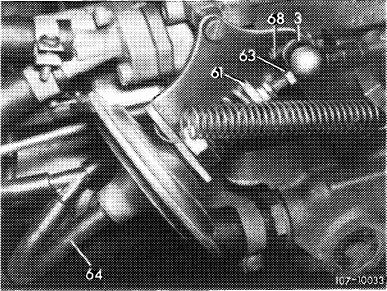
1 Check connecting pipe and diaphragm for leaks. For this purpose, pinch vacuum hose at vent valve. If vacuum is now available, attach connecting pipe by glueing with Omnifit or renew diaphragm, respectively.
2 Check all vacuum hoses up to intake pipe for correct layout, condition and tight seat and recondition, if required.
3 Check electric switchover valve (37). For this purpose, switch ignition on and off. The operating noise should now be heard or felt. If not, check whether with the ignition switched on the plug is energized and connected to ground. Renew fuse or establish ground connection, as required. If everything is in order and the switchover valve is nevertheless not yet switching, renew valve since a mechanical defect is indicated.
|
||||
|
|
||||
 |
 |
|||
|
|
||||
|
07.2.2 la-182/2
|
||||
|
|
||||
|
|
|||
 |
 |
||
|
107-9048
|
|||
 |
|||
 |
|||
|
|
|||
|
|
||||
|
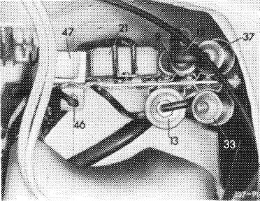
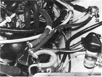
B. ©1975/76, (D1976
|
||||
|
|
||||
 |
||||
|
|
||||
|
Test conditions:
|
All electric fuses in order. Engine at operating temperature. Sealing at vacuum end of decel diverter valve (41) and switchover valve (33), as well as their function in order.
|
|||
|
|
||||
|
Connect vacuum tester. Run engine at idle speed, vacuum should be indicated.
|
 |
|||
|
Vacuum in order.
|
No vacuum.
|
|||
 |
i
|
|||
|
|
||||
|
07.2.2 la—182/4
|
||||
|
|
||||
|
|
|||
|
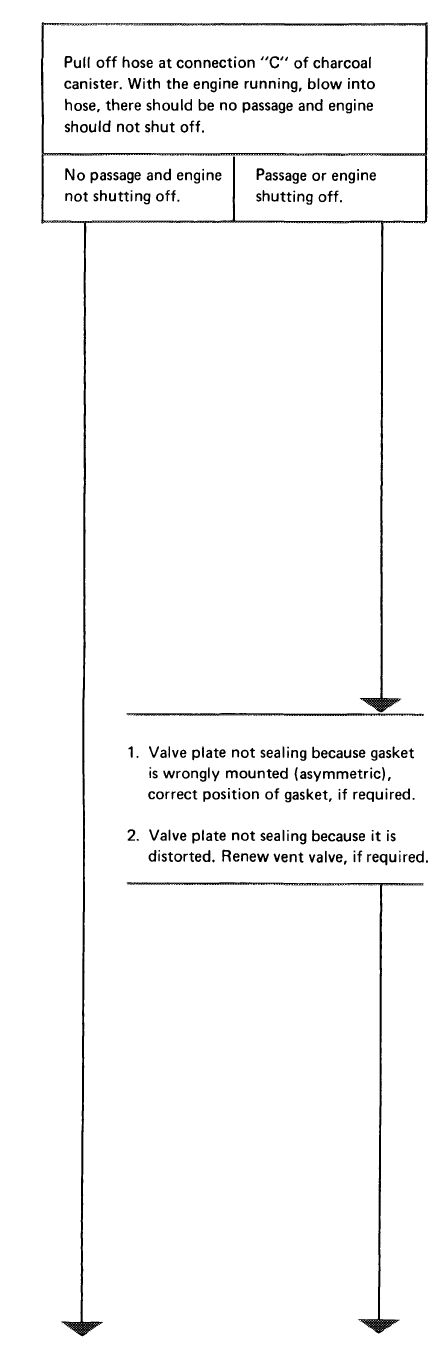
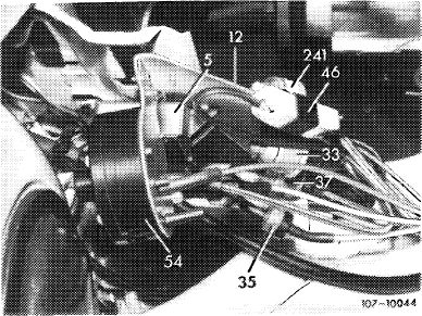
1. Check connecting pipe and diaphragm for leaks. For this purpose, pinch vacuum hose at vent valve. If vacuum is now available, attach connecting pipe, glue in with Omnifit or renew diaphragm, as required.
2. Check all vacuum hoses up to vacuum governor for correct layout, condition and tight seat and recondition, if required.
|
|||
|
|
|||
|
3. Check electric switchover valve (37). For this purpose, switch ignition on and off, the operating noise should now be heard or felt. If not, check whether with the ignition switched on the plug is energized and connected to ground. Renew fuse, if required or establish ground connection. If everything is in order and the switchover valve is nevertheless not switching, renew valve since a mechanical defect is indicated.
|
M7-0004CJU
iv.
|
||
|
|
|||
|
107-10044
|
|||
|
|
|||
|
07.2.2 la-182/5
|
|||
|
|
|||
|
|
|||
 |
 |
||
 |
|||
 |
|||
|
|
|||
|
07.2.2 la-182/6
|
|||
|
|
|||
|
|
|||
 |
 |
||
 |
|||
|
|
|||
|
07.2.2 la-182/7
|
|||
|
|
|||