Renewal of valve seat rings
|
|
||||||||||||||||||||||||||||||||||||||||||||||||||||||||||||||||||||||||||||||||||||
|
05—290 Renewal of valve seat rings
|
||||||||||||||||||||||||||||||||||||||||||||||||||||||||||||||||||||||||||||||||||||
|
|
||||||||||||||||||||||||||||||||||||||||||||||||||||||||||||||||||||||||||||||||||||
|
Data
|
||||||||||||||||||||||||||||||||||||||||||||||||||||||||||||||||||||||||||||||||||||
|
|
||||||||||||||||||||||||||||||||||||||||||||||||||||||||||||||||||||||||||||||||||||
|
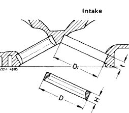
Overlap of valve seat rings in cylinder head
|
0.08-0.10
|
|||||||||||||||||||||||||||||||||||||||||||||||||||||||||||||||||||||||||||||||||||
|
|
||||||||||||||||||||||||||||||||||||||||||||||||||||||||||||||||||||||||||||||||||||
|
 |
|||||||||||||||||||||||||||||||||||||||||||||||||||||||||||||||||||||||||||||||||||
|
H
|
8.60 8.51
|
|||||||||||||||||||||||||||||||||||||||||||||||||||||||||||||||||||||||||||||||||||
|
|
||||||||||||||||||||||||||||||||||||||||||||||||||||||||||||||||||||||||||||||||||||
|
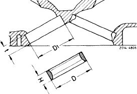
Exhaust
|
|||||||||||||||||||||||||||||||||||||||||||||||||||||||||||||||||||||||||||||||||||
 |
||||||||||||||||||||||||||||||||||||||||||||||||||||||||||||||||||||||||||||||||||||
|
H
|
10.50 10.39
|
|||||||||||||||||||||||||||||||||||||||||||||||||||||||||||||||||||||||||||||||||||
|
|
||||||||||||||||||||||||||||||||||||||||||||||||||||||||||||||||||||||||||||||||||||
|
M Series (except emission-controlled engines) starting April 1978. Emission-controlled engines starting model year 1980. Conventional tools
|
||||||||||||||||||||||||||||||||||||||||||||||||||||||||||||||||||||||||||||||||||||
|
|
||||||||||||||||||||||||||||||||||||||||||||||||||||||||||||||||||||||||||||||||||||
|
Plug gauge 9 mm dia. for intake and exhaust valve guide
|
116 589 08 21 00
|
|||||||||||||||||||||||||||||||||||||||||||||||||||||||||||||||||||||||||||||||||||
|
|
||||||||||||||||||||||||||||||||||||||||||||||||||||||||||||||||||||||||||||||||||||
|
||||||||||||||||||||||||||||||||||||||||||||||||||||||||||||||||||||||||||||||||||||
|
|
||||||||||||||||||||||||||||||||||||||||||||||||||||||||||||||||||||||||||||||||||||
|
05.2-290/1 F3
|
||||||||||||||||||||||||||||||||||||||||||||||||||||||||||||||||||||||||||||||||||||
|
|
||||||||||||||||||||||||||||||||||||||||||||||||||||||||||||||||||||||||||||||||||||
|
|
|||
|
Internal micrometer (range 25—60 mm)
|
e.g. made by Mahr, D-7300 Esslingen order No. 844
|
||
|
|
|||
|
External micrometer (range 25—50 mm)
|
e.g. made by Mahr, D-7300 Esslingen order No. 40 S
|
||
|
|
|||
|
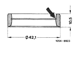
Note
|
 |
||
|
Exhaust valve seat rings for unleaded fuel with red or blue color dot on inside may be installed only in USA engines starting model year 1975. Starting model year 1980 these valve seat rings are identified by a machined groove (arrow).
|
|||
|
|
|||
|
Replacing
|
|||
|
|
|||
|
1 Unscrew old valve seat ring by means of ring seat machining tool.
2 Check valve guides, replacing if necessary (05-285).
|
 |
||
|
|
|||
|
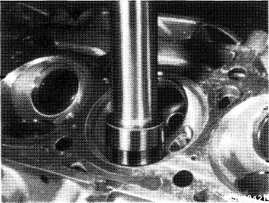
3 Measure basic bore D1.
A new standard size valve seat insert can be used, if the specified overlap is given.
4 Machine basic bore repair stage D1 with ring seat machining tool in such a manner that bore is just cleaned.
5 Measure machined basic bore.
6 Provide specified overlap by machining the oversize valve seat inserts.
|
|||
|
|
|||
|
05.2-290/2 F3
|
|||
|
|
|||
|
|
|||
|
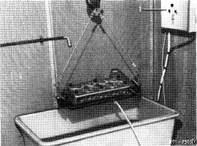
7 Heat cylinder head in water to approx. 80 C (176 °F).
8 Undercool valve seat insert with fluid air.
|
 |
||
|
|
|||
|
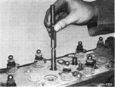
9 Knock in valve seat insert with a pertinent mandrel.
|
 |
||
|
10 Machine valve seats (05-291).
|
|||
|
|
|||
|
05.2-290/3 F3
|
|||
|
|
|||