Inspecting, assigning and installing valve guides
|
|
||||||||||||||||||||||||||||||||||||||||||||||||||||||||||||||||||||||||||||||||
|
05—285 Inspecting, assigning and installing valve guides
|
||||||||||||||||||||||||||||||||||||||||||||||||||||||||||||||||||||||||||||||||
|
|
||||||||||||||||||||||||||||||||||||||||||||||||||||||||||||||||||||||||||||||||
|
Valve guides
|
||||||||||||||||||||||||||||||||||||||||||||||||||||||||||||||||||||||||||||||||
|
|
||||||||||||||||||||||||||||||||||||||||||||||||||||||||||||||||||||||||||||||||
|
Step settings and part no.
|
OD
|
Color code
|
Basic bore in cylinder head
|
Code number in cylinder head l)
|
Valve guide ID
|
|||||||||||||||||||||||||||||||||||||||||||||||||||||||||||||||||||||||||||
|
|
||||||||||||||||||||||||||||||||||||||||||||||||||||||||||||||||||||||||||||||||
|
||||||||||||||||||||||||||||||||||||||||||||||||||||||||||||||||||||||||||||||||
|
|
||||||||||||||||||||||||||||||||||||||||||||||||||||||||||||||||||||||||||||||||
|
1st repair stage 110 050 35 24
|
15.216-15.233
|
red
|
15.200-15.218
|
|||||||||||||||||||||||||||||||||||||||||||||||||||||||||||||||||||||||||||||
|
|
||||||||||||||||||||||||||||||||||||||||||||||||||||||||||||||||||||||||||||||||
|
2nd repair stage 110 050 36 24
|
15.416-15.433
|
white
|
15.400-15.418
|
|||||||||||||||||||||||||||||||||||||||||||||||||||||||||||||||||||||||||||||
|
|
||||||||||||||||||||||||||||||||||||||||||||||||||||||||||||||||||||||||||||||||
|
3rd repair stage 110 050 37 24
|
16.2
(roughing dim.)2)
|
16.000-16.018
|
||||||||||||||||||||||||||||||||||||||||||||||||||||||||||||||||||||||||||||||
|
|
||||||||||||||||||||||||||||||||||||||||||||||||||||||||||||||||||||||||||||||||
|
Standard dimension 110 050 40 24
|
15.016-15.023 15.021-15.028 15.026-15.033
|
green
without
brown
|
15.000-15.006 1 15.007-15.012 2 15.013-15.018 3
|
|||||||||||||||||||||||||||||||||||||||||||||||||||||||||||||||||||||||||||||
|
|
||||||||||||||||||||||||||||||||||||||||||||||||||||||||||||||||||||||||||||||||
|
Intermediate stage 110 050 41 24
|
15.034-15.040 15.039-15.046
|
gray-green gray
|
||||||||||||||||||||||||||||||||||||||||||||||||||||||||||||||||||||||||||||||
|
|
||||||||||||||||||||||||||||||||||||||||||||||||||||||||||||||||||||||||||||||||
|
9.000-9.015
|
|||||||||||||||||||||||||||||||||||||||||||||||||||||||||||||||||||||||||||||||
|
|
||||||||||||||||||||||||||||||||||||||||||||||||||||||||||||||||||||||||||||||||
|
3rd repair stage 110 050 44 24
|
16.2
(roughing dim.)2)
|
16.000-16.018
|
||||||||||||||||||||||||||||||||||||||||||||||||||||||||||||||||||||||||||||||
|
|
||||||||||||||||||||||||||||||||||||||||||||||||||||||||||||||||||||||||||||||||
|
For overlap of valve guide in cylinder head refer to table: Association basic bore valve guide
M After kocking-out valve guide, the basic bore is not essentially larger than the series basic bore. On exchange engines the basic
bore is machined and does not correspond to series basic bore. 3» For machining OD 16.016-16.033. ’ Series (except emisssion-controlled engines) starting April 1978. Emission-controlled engines starting model year 1980.
|
||||||||||||||||||||||||||||||||||||||||||||||||||||||||||||||||||||||||||||||||
|
|
||||||||||||||||||||||||||||||||||||||||||||||||||||||||||||||||||||||||||||||||
|
Special tools
|
||||||||||||||||||||||||||||||||||||||||||||||||||||||||||||||||||||||||||||||||
|
|
||||||||||||||||||||||||||||||||||||||||||||||||||||||||||||||||||||||||||||||||
|
Master mandrel 9 mm dia. intake and exhaust
|
116 589 08 21 00
|
|||||||||||||||||||||||||||||||||||||||||||||||||||||||||||||||||||||||||||||||
|
|
||||||||||||||||||||||||||||||||||||||||||||||||||||||||||||||||||||||||||||||||
|
Master mandrel 11 mm dia. exhaust
|
116 589 09 21 00
|
|||||||||||||||||||||||||||||||||||||||||||||||||||||||||||||||||||||||||||||||
|
|
||||||||||||||||||||||||||||||||||||||||||||||||||||||||||||||||||||||||||||||||
|
05.2-285/1 F3
|
||||||||||||||||||||||||||||||||||||||||||||||||||||||||||||||||||||||||||||||||
|
|
||||||||||||||||||||||||||||||||||||||||||||||||||||||||||||||||||||||||||||||||
|
|
||||
|
Knock-out mandrel 9 mm dia. intake and exhaust
|
110 589 02 15 00
|
|||
|
|
||||
|
Knock-out mandrel 11 mm dia exhaust
|
110 589 03 15 00
|
|||
|
|
||||
|
Knock-in mandrel 9 mm dia. intake
|
116 589 20 15 00
|
|||
|
|
||||
|
Knock-in mandrel 11 mm dia. exhaust’)
|
116 589 19 15 00
|
|||
|
|
||||
|
Reamer 8.99 mm dia. H 7 intake and exhaust
|
000 589 10 53 00
|
|||
|
|
||||
|
Reamer 10.99 mm dia. H 7 exhaust
|
000 589 15 53 00
|
|||
|
|
||||
|
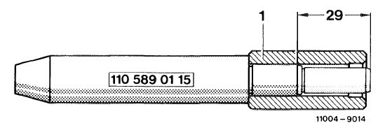
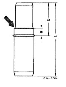
’) Change former knock-in mandrel 110 589 01 15 00 according to following drawing, so that exhaust valve guides with 9 mm ID can also be knocked-in. Press-off sleeve (1), machine guide pin (dimension 29 mm), press sleeve (1) on again.
|
||||
|
|
||||
|
Conventional tool
|
 |
|||
|
|
||||
|
Internal precision measuring instrument 8—12 mm dia.
|
e.g. made by Hommel, D-5000 Koln 71 Subito, order no. 33 830 103
|
|||
|
|
||||
|
Note
|
||||
|
|
||||
|
Valve guides which must be renewed due to wear, should permit installation in original basic bore in cylinder head without additional machining.
Valve guides which are loosely seated in cylinder head must be inserted in newly made basic bores.
|
||||
|
|
||||
|
Checking valve guide
|
 |
|||
|
Upon removal of valve spring and valve stem seal, the wear on valve guide can be determined in installed condition by moving valve stem predominantly crosswise in relation to engine.
As a reference value, a max. wear of approx. 1.2 for 1000 km (0.12 mm for 100 000 km) should be assumed.
|
||||
|
|
||||
|
05.2-285/2 F3
|
||||
|
|
||||
|
|
|||
|
However, this value does not apply to upper and lower range of valve guide, since experience has shown that the wear at these points is higher.
Check valve guides with inspection mandrel and cylinder head disassembled.
Valve guides, which are worn outside on seat of valve stem seal, should be replaced, since the valve stem seal is no longer tightly seated.
|
 |
||
|
|
|||
|
Assigning and inserting valve guides
|
 |
||
|
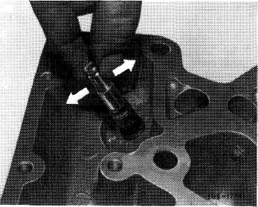
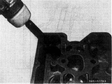
1 Knock-out valve guide with knock-out mandrel from direction of combustion chamber or press out.
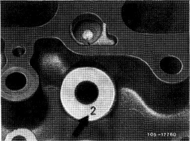
2 Visually check basic bore in cylinder head for score marks and deposits.
Equalize deposits (if any) by means of a small file.
|
|||
|
|
|||
|
Attention!
A basic bore with punched-in code number, e.g. 2 (arrow) should be associated with the respective valve guide with regard to the applied color code or the measured OD.
|
 |
||
|
|
|||
|
On exchange engines the basic bore in cylinder head is larger than normal. This means, that the punched-in code numbers in cylinder head are no longer in accordance with basic bores according to table.
In such a case, measure basic bore or OD of knocked-out valve guide prior to pertinent association.
|
|||
|
|
|||
|
05.2-285/3 F3
|
|||
|
|
|||
|
|
||||||
|
Association of a valve guide with a not-refinished basic bore in cylinder head
|
||||||
|
|
||||||
|
Punched-in code Color code
number adjacent of valve
to basic bore in guide2) cylinder head1)
|
Overlap in cylinder head
|
Machining note
|
||||
|
|
||||||
|
without
|
0.015-0.028
|
Knock-in valve guide with knock-in mandrel.
|
||||
|
|
||||||
|
0
|
brown
|
0.020-0.027
|
Undercool valve guide, knock-in with knock-in mandrel or heat cylinder head, knock-in with knock-in mandrel.
|
|||
|
|
||||||
|
gray-green
|
3) 0.028-0.040
|
Undercool valve guide, knock-in with knock-in mandrel, ream ID or heat cylinder head, knock-in, ream ID with reamer.
|
||||
|
|
||||||
|
brown
|
0.019-0.026
|
Knock-in valve guide with knock-in mandrel.
|
||||
|
|
||||||
|
1
|
gray-green
|
0.022-0.033
|
Undercool valve guide, knock-in with knock-in mandrel or heat cylinder head, knock-in with knock-in mandrel.
|
|||
|
|
||||||
|
gray3)
|
0.027-0.039
|
Undercool valve guide, knock-in with knock-in mandrel, ream ID or heat cylinder head, knock-in, ream ID with reamer.
|
||||
|
|
||||||
|
gray-green
|
0.016-0.027
|
Knock-in valve guide with knock-in mandrel.
|
||||
|
|
||||||
|
2
|
gray
|
0.021-0.033
|
Undercool valve guide, knock-in with knock-in mandrel or heat cylinder head, knock-in with knock-in mandrel.
|
|||
|
|
||||||
|
gray-brown3)4) 0.027-0.038
|
Undercool valve guide, knock-in with knock-in mandrel, ream ID or heat cylinder head, knock-in, ream with reamer.
|
|||||
|
|
||||||
|
M After knocking-out valve guide, the basic bore is not essentially larger than the series basic bore. On exchange engines the basic bore is machined and does no longer correspond to series bore.
2) Valve guides with color code „green”, overlap 0.010—0.023 mm, should not be used since they may become loose.
3) Use valve guides which require inside reaming after knocking-in, should be used only if no other valve guides are available.
4) Valve guide gray-brown with 0.027—0.038 mm overlap, may also be installed into cylinder head instead of a slightly loose valve guide without refinishing basic bore.
|
||||||
|
|
||||||
|
05.2-285/4 F3
|
||||||
|
|
||||||
|
|
||||||||||||||||||||||||||||||||||
|
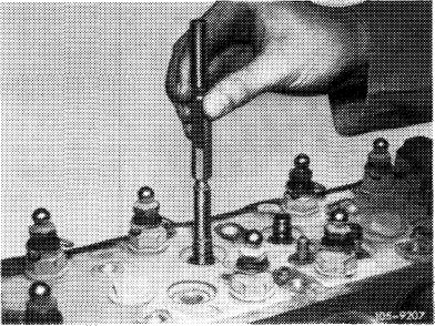
3 Insert valve guide for approx. 3—4 minutes into liquid oxygen, then insert immediately into knock-in mandrel and immediately into respective bore while following-up with a hammer.
Note: If the valve guide is not knocked-in immediately up to locking ring, it will absorb the temperature of the cylinder head and can then be completely knocked-in with considerable difficulty.
|
 |
|||||||||||||||||||||||||||||||||
|
|
||||||||||||||||||||||||||||||||||
|
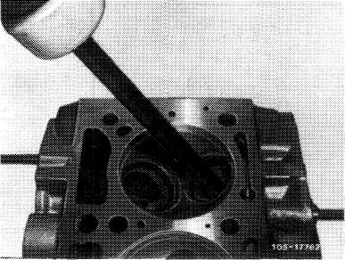
4 If no liquid oxygen is available, heat cylinder head in a water bath, e.g. a parts washing system or a heating oven to max. 80 °C (176 °F).
5 Coat valve guide with tallow and knock-in with knock-in mandrel until circlip or knock-in mandrel rests against cylinder head.
|
||||||||||||||||||||||||||||||||||
|
|
||||||||||||||||||||||||||||||||||
|
Attention!
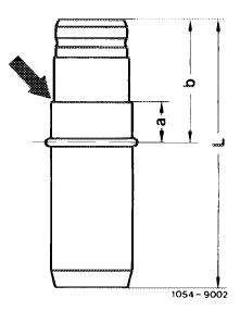
Use specified knock-in mandrel only.
The stop in knock-in mandrel is adapted to valve guide and dimension a in such a manner that the valve guide can be knocked into end position without damage.
|
 |
|||||||||||||||||||||||||||||||||
|
Intake valve guide
|
||||||||||||||||||||||||||||||||||
|
|
||||||||||||||||||||||||||||||||||
|
 |
|||||||||||||||||||||||||||||||||
|
ID
|
9 starting April 1978 starting (usa) 1980
|
|||||||||||||||||||||||||||||||||
|
11 up to April 1978 up to <@) 1980
|
||||||||||||||||||||||||||||||||||
|
Exhaust valve guide
|
||||||||||||||||||||||||||||||||||
|
|
||||||||||||||||||||||||||||||||||
|
05.2-285/5 F3
|
||||||||||||||||||||||||||||||||||
|
|
||||||||||||||||||||||||||||||||||