Machining valve seats
|
|
||||||||||||||||||||||||||||||||
|
05—291 Machining valve seats
|
||||||||||||||||||||||||||||||||
|
|
||||||||||||||||||||||||||||||||
|
Data
|
Intake
|
Exhaust
|
||||||||||||||||||||||||||||||
|
|
||||||||||||||||||||||||||||||||
|
Valve seat width a
|
1.8-2.5
|
1.5-2.0
|
 |
|||||||||||||||||||||||||||||
|
||||||||||||||||||||||||||||||||
|
Permissible runout of valve seat
|
0.05
|
|||||||||||||||||||||||||||||||
|
|
||||||||||||||||||||||||||||||||
|
Minimum distance A with new valves and new valve seats, cylinder head parting surface not machined
|
Minimum distance A with new valves and new valve seats, cylinder head parting surface 0.4 mm milled off
|
|||||||||||||||||||||||||||||||
|
|
||||||||||||||||||||||||||||||||
|
Intake
|
3.3
|
2.9
|
||||||||||||||||||||||||||||||
|
|
||||||||||||||||||||||||||||||||
|
Valve retainer dia. 37 mm 0.6
|
0.2
|
|||||||||||||||||||||||||||||||
|
|
||||||||||||||||||||||||||||||||
|
Exhaust
|
||||||||||||||||||||||||||||||||
|
|
||||||||||||||||||||||||||||||||
|
Valve retainer dia. 39 mm 0.04
|
0.36 standout
|
|||||||||||||||||||||||||||||||
|
|
||||||||||||||||||||||||||||||||
|
Max. distance A with new valves and machined valve seats, cylinder head parting surface not machined
|
Max. distance A with new valves and machined valve seats, cylinder head parting surface 0.4 mm milled off
|
|||||||||||||||||||||||||||||||
|
|
||||||||||||||||||||||||||||||||
|
Intake
|
4.2
|
3.8
|
||||||||||||||||||||||||||||||
|
|
||||||||||||||||||||||||||||||||
|
Valve retainer dia. 37 mm 1.5
|
1.1
|
|||||||||||||||||||||||||||||||
|
|
||||||||||||||||||||||||||||||||
|
Exhaust
|
||||||||||||||||||||||||||||||||
|
|
||||||||||||||||||||||||||||||||
|
Valve retainer dia. 39 mm 0.94
|
0.54
|
|||||||||||||||||||||||||||||||
|
|
||||||||||||||||||||||||||||||||
|
Max. distance A is reduced by the same dimension by which the cylinder head parting surface has been machined down.
|
||||||||||||||||||||||||||||||||
|
|
||||||||||||||||||||||||||||||||
 |
||||||||||||||||||||||||||||||||
|
|
||||||||||||||||||||||||||||||||
|
Special tools
|
||||||||||||||||||||||||||||||||
|
|
||||||||||||||||||||||||||||||||
|
Magnetic lifter for valve cone halves
|
116 589 06 63 00
|
|||||||||||||||||||||||||||||||
|
|
||||||||||||||||||||||||||||||||
|
Master mandrel 9 mm dia. for intake and exhaust valve guide
Master mandrel 11 mm dia. for exhaust valve guide
|
116 589 08 21 00 116 589 09 21 00
|
|||||||||||||||||||||||||||||||
|
|
||||||||||||||||||||||||||||||||
|
05.2-291/1 F3
|
||||||||||||||||||||||||||||||||
|
|
||||||||||||||||||||||||||||||||
|
|
||||
|
Conventional tools
|
||||
|
|
||||
|
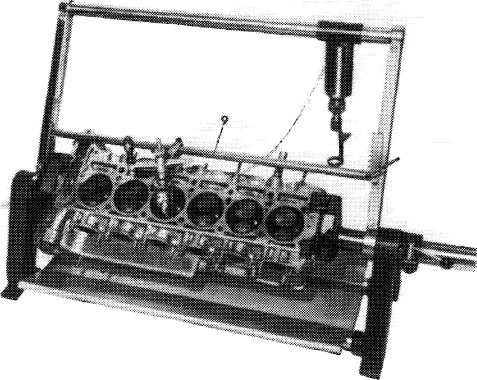
Cylinder head clamping device
|
e.g. made by Rothenberger, D-6233 Kelkheim order no. 2.9900
|
|||
|
|
||||
|
Valve seat machining tool
|
e.g. made by Hunger, D-8000 Miinchen type VDSNL 1/45/30 order No. 236.00.308
|
|||
|
|
||||
|
Test set for valve seats
|
e.g. made by Hunger, D-8000 Miinchen order No. 216.93.300
|
|||
|
|
||||
|
60° correcting bit No. 13 for bottom correction angle
|
e.g. made by Hunger, D-8000 Munchen order No. 216.64.622
|
|||
|
|
||||
|
Note
|
 |
|||
|
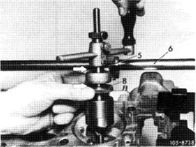
Clamp cylinder head in clamping device for disassembly and machining.
Machine valve seats with valve seat machining tool, valve seat grinding machine or with a valve seat cutter.
|
||||
|
|
||||
|
|
||||
|
Machining valve seats
|
 |
|||
|
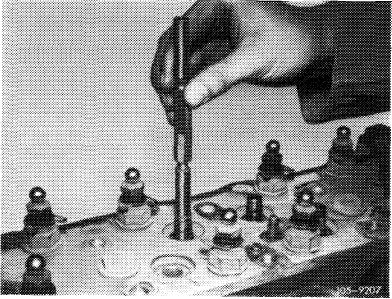
1 Check valve guides, replacing if necessary (05—295).
|
||||
|
|
||||
|
05.2-291/2 F3
|
||||
|
|
||||
|
|
|||
|
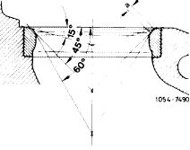
2 Machine valve seat (45°) according to instructions of tool manufacturer.
Attention!
First loosen pilot after runout of valve seat has been checked (point 5).
|
 |
||
|
|
|||
|
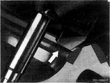
3 Correct bottom of valve seat to 60°.
Attention!
Do not machine bead (arrow) on lower part of valve seat.
|
 |
||
|
|
|||
|
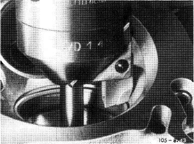
4 Measure valve seat width, and, if necessary, correct top to 15°.
|
 |
||
|
|
|||
|
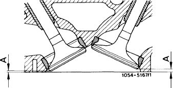
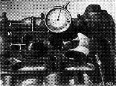
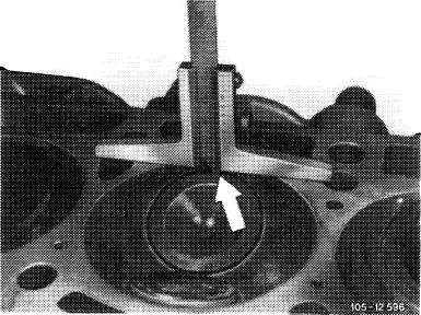
5 Check valve seat runout.
This requires sliding test sleeve (17) with dial gage holder (16) and dial gage on to pilot, and turning test sleeve. In so doing the permissible runout must not exceed 0.05 mm.
|
 |
||
|
13 Pilot
16 Dial gage holder
1 7 Test sleeve
|
|||
|
|
|||
|
05.2-291/3 F3
|
|||
|
|
|||
|
|
|||
|
6 Guide in new valve and check max. distance A (arrow).
If necessary, replace valve seat insert (05—140).
|
 |
||
|
|
|||
|
05.2-291/4 F3
|
|||
|
|
|||