Removal and installation of slide rails
|
|
|||||||||||||||||||||||||||||||||||||||||||||
|
05—340 Removal and installation of slide rails
|
|||||||||||||||||||||||||||||||||||||||||||||
|
|
|||||||||||||||||||||||||||||||||||||||||||||
|
|||||||||||||||||||||||||||||||||||||||||||||
|
|
|||||||||||||||||||||||||||||||||||||||||||||
|
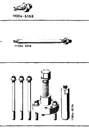
Impact extractor for bearing pin (basic unit)
|
 |
116 589 20 33 00
|
|||||||||||||||||||||||||||||||||||||||||||
|
|
|||||||||||||||||||||||||||||||||||||||||||||
|
Bolt 6 x 50 for impact extractor
|
 |
116 589 01 34 00
|
|||||||||||||||||||||||||||||||||||||||||||
|
Bolt 6 x 150 for impact extractor
|
116 589 02 34 00
|
||||||||||||||||||||||||||||||||||||||||||||
|
Bolt 10 x 100 for impact extractor
|
116 589 03 34 00
|
||||||||||||||||||||||||||||||||||||||||||||
|
Balance disc extractor
|
116 589 10 33 00
|
||||||||||||||||||||||||||||||||||||||||||||
|
|
|||||||||||||||||||||||||||||||||||||||||||||
|
Rigid chain tensioner
|
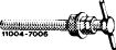 |
110 589 03 31 00
|
|||||||||||||||||||||||||||||||||||||||||||
|
|
|||||||||||||||||||||||||||||||||||||||||||||
|
Chain tensioner holder
|
|
rTi?
|
110 589 02 31 00
|
||||||||||||||||||||||||||||||||||||||||||
|
N,
|
|||||||||||||||||||||||||||||||||||||||||||||
|
|
|||||||||||||||||||||||||||||||||||||||||||||
|
Holder
|
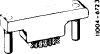 |
116 589 01 40 00
|
|||||||||||||||||||||||||||||||||||||||||||
|
|
|||||||||||||||||||||||||||||||||||||||||||||
|
05.2-340/1 F3
|
|||||||||||||||||||||||||||||||||||||||||||||
|
|
|||||||||||||||||||||||||||||||||||||||||||||
|
|
|||
|
Sliding rail (2) in camshaft housing
|
 |
||
|
1 Remove valve cover and knock out sliding rail pin with an impact extractor.
Remove sliding rail.
2 Watch position of sliding rail when installing.
Coat collar of sliding rail pin with a sealing compound.
|
|||
|
|
|||
|
Sliding rail (2a) in cylinder head
|
 |
||
|
1 Remove radiator.
2 Remove chain tensioner or spring in chain tensioner (05-310).
3 Mark relation of camshaft sprockets and timing chain with paint.
4 Remove sliding rail (2) in camshaft housing.
|
|||
|
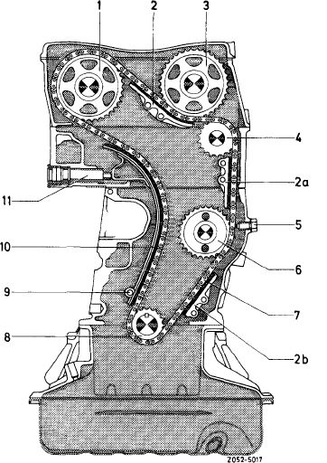
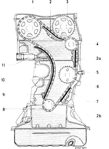
Chain drive
1 Exhaust camshaft sprocket 2-2b Sliding rail
3 Intake camshaft sprocket
4 Guide wheel
5 Lock screw
6 Intermediate wheel
7 Timing chain
8 Crankshaft sprocket
9 Tensioning rail bearing pin
10 Tensioning rail
11 Hydraulic chain tensioner
|
|||
|
|
|||
|
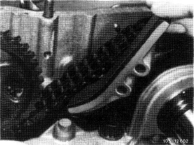
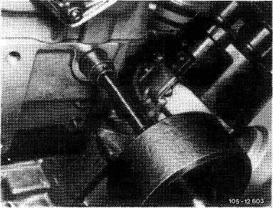
5 Connect a wire hook (5 mm thick) to guide wheel (4) and knock out the bearing pin with an impact extractor (10 mm bolt). Remove guide wheel.
|
 |
||
|
|
|||
|
05.2-340/2
|
|||
|
|
|||
|
|
|||
|
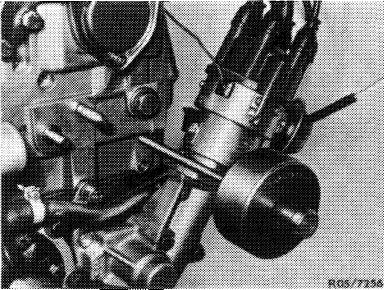
6 Knock out sliding rail pin with an impact extractor and pull out sliding rail with a wire hook.
7 Installation in reverse sequence of removal.
|
 |
||
|
|
|||
|
Sliding rail (2b) in crankcase
|
 |
||
|
1 Remove radiator.
2 Remove entire oil pan (01—310).
3 Remove vibration damper and balance disc (03—340).
4 Mark relation of camshaft sprockets and timing chain with paint.
5 Remove sliding rail (2) and guide wheel (4).
6 Remove chain tensioner or compression spring (05-310).
7 Knock out sliding rail pin with an impact extractor and remove sliding rail.
8 Installation in reverse sequence of removal.
|
|||
|
|
|||
|
05.2-340/3 F3
|
|||
|
|
|||