Removal and installation of helical gear shaft
|
|
|||||||||||||||||||||||||||||||||||||||||||||||||||||||||||||||||||||||||||||||||||||||||||||||||||||||||||||||||||||||||||||||||||||||||||||
|
05—410 Removal and installation of helical gear shaft
|
|||||||||||||||||||||||||||||||||||||||||||||||||||||||||||||||||||||||||||||||||||||||||||||||||||||||||||||||||||||||||||||||||||||||||||||
|
|
|||||||||||||||||||||||||||||||||||||||||||||||||||||||||||||||||||||||||||||||||||||||||||||||||||||||||||||||||||||||||||||||||||||||||||||
|
Special tools
|
|||||||||||||||||||||||||||||||||||||||||||||||||||||||||||||||||||||||||||||||||||||||||||||||||||||||||||||||||||||||||||||||||||||||||||||
|
|
|||||||||||||||||||||||||||||||||||||||||||||||||||||||||||||||||||||||||||||||||||||||||||||||||||||||||||||||||||||||||||||||||||||||||||||
|
Impact puller for bearing bolt (basic unit)
|
 |
116 589 20 33 00
|
|||||||||||||||||||||||||||||||||||||||||||||||||||||||||||||||||||||||||||||||||||||||||||||||||||||||||||||||||||||||||||||||||||||||||||
|
|
|||||||||||||||||||||||||||||||||||||||||||||||||||||||||||||||||||||||||||||||||||||||||||||||||||||||||||||||||||||||||||||||||||||||||||||
|
Threaded bolt M 6 x 150 for impact puller
|
1,4,
|
116 589 02 34 00
|
|||||||||||||||||||||||||||||||||||||||||||||||||||||||||||||||||||||||||||||||||||||||||||||||||||||||||||||||||||||||||||||||||||||||||||
|
|
|||||||||||||||||||||||||||||||||||||||||||||||||||||||||||||||||||||||||||||||||||||||||||||||||||||||||||||||||||||||||||||||||||||||||||||
|
Note
|
 |
||||||||||||||||||||||||||||||||||||||||||||||||||||||||||||||||||||||||||||||||||||||||||||||||||||||||||||||||||||||||||||||||||||||||||||
|
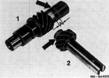
The oil pump drive comprises the intermediate gear shaft (1) and the helical gear shaft (2), and may be replaced in sets only (05—412).
In the event of repairs, install oil pump drive part no. 110 050 02 06:
Intermediate gear (1): 9 teeth, groove (arrow), dimension A = 5 mm Helical gear (2): 12 teeth, groove (arrow).
|
|||||||||||||||||||||||||||||||||||||||||||||||||||||||||||||||||||||||||||||||||||||||||||||||||||||||||||||||||||||||||||||||||||||||||||||
|
|
|||||||||||||||||||||||||||||||||||||||||||||||||||||||||||||||||||||||||||||||||||||||||||||||||||||||||||||||||||||||||||||||||||||||||||||
|
Standard installation oil pump drive 110 050 02 06
|
|||||||||||||||||||||||||||||||||||||||||||||||||||||||||||||||||||||||||||||||||||||||||||||||||||||||||||||||||||||||||||||||||||||||||||||
|
|
|||||||||||||||||||||||||||||||||||||||||||||||||||||||||||||||||||||||||||||||||||||||||||||||||||||||||||||||||||||||||||||||||||||||||||||
|
|||||||||||||||||||||||||||||||||||||||||||||||||||||||||||||||||||||||||||||||||||||||||||||||||||||||||||||||||||||||||||||||||||||||||||||
|
|
|||||||||||||||||||||||||||||||||||||||||||||||||||||||||||||||||||||||||||||||||||||||||||||||||||||||||||||||||||||||||||||||||||||||||||||
|
|
||||
|
110.985- 10– 12-
110.986- 10-
|
002060(1. 1977) 009179(1. 1977)
000461 (1. 1977) 000991 (1. 1977)
|
|||
|
|
||||
|
All exchange engines starting unit no. 464 130 are provided with oil pump drive part no. 110 050 02 06.
|
||||
|
|
||||
|
Removal
|
 |
|||
|
1 Remove intake pipe (09-400).
2 Knock out closing cover by means of impact puller (6 mm threaded bolt).
|
||||
|
|
||||
|
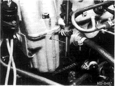
3 Pull out helical gear shaft (4) in upward direction by means of an M-6 screw.
Note: The bearing body together with bearing bushing for helical gear shaft can be knocked out in upward direction with intermediate gear shaft removed.
|
 |
|||
|
|
||||
|
05.2-410/2 F2
|
||||
|
|
||||
|
|
|||
|
Installation
|
 |
||
|
4 Guide in helical gear shaft (4).
Oil pump drive shaft (9) must engage in dog claws of helical gear shaft (4).
5 Knock in new cover (2) with a pertinent sleeve (approx. 35 mm dia.).
6 Install intake manifold with a new gasket (09—400).
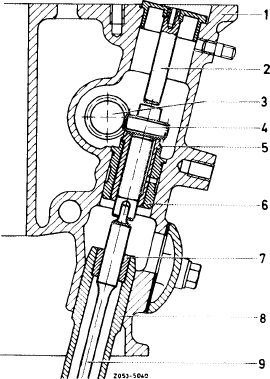
Oil pump drive
1 Crankcase
2 Cover with stop pin
3 Intermediate gear shaft of oil pump drive
4 Helical gear shaft of oil pump drive
5 Bearing bushing
6 Bearing
7 Bearing bushing of oil pump housing
8 Oil pump housing
9 Oil pump drive shaft
|
|||
|
|
|||
|
05.2-410/3 F2
|
|||
|
|
|||