Removal and installation of rocker arms
|
|
|||||||
|
05—230 Removal and installation of rocker arms
|
|||||||
|
|
|||||||
|
Valve clearance
|
Cold engine (ca. 20 °C)
|
Warm engine (60 °C± 15°C)
|
|||||
|
|
|||||||
|
Intake
|
0.101)
|
0.151)
|
|||||
|
|
|||||||
|
Exhaust
|
0.25
|
0.30
|
|||||
|
|
|||||||
|
„M 0.05 mm more for consistent outside temperatures below —20 °C.
|
|||||||
|
|
|||||||
|
Tightening torque
|
Nm
|
(kpm)
|
|||||
|
|
|||||||
|
Cylinder head cover bolts and capped nuts
|
(0.5)
|
||||||
|
|
|||||||
|
Special tools
|
|||||||
|
|
|||||||
|
Depressor for valve spring
|
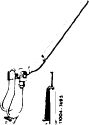 |
110 589 04 61 00
|
|||||
|
|
|||||||
|
Valve adjusting wrench, 17 mm
|
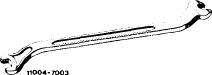 |
110 589 01 01 00
|
|||||
|
|
|||||||
|
Contact grip to turn engine (Part of compression recorder 001 589 46 21 00)
|
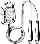 |
001 589 46 21 08
|
|||||
|
11004 -6467
|
|||||||
|
|
|||||||
|
Note
|
|||||||
|
|
|||||||
|
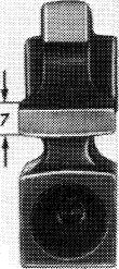
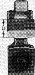
1st version rocker arm, guiding surface 7 mm. 2nd version rocker arm, guiding surface 14 mm.
A 1st version rocker arm is replaced by a 2nd version rocker arm when repairing.
|
 |
 |
|||||
|
|
|||||||
|
55 Q5/7S94
|
|||||||
|
|
|||||||
|
05.2-230/1 F3
|
|||||||
|
|
|||||||
|
|
|||
|
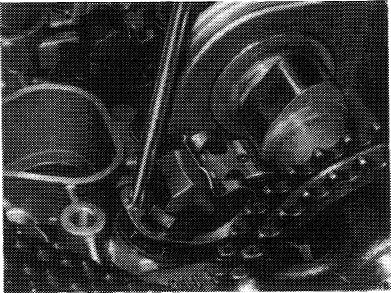
Attention!
The rocker arms and spring clamps of engines 110 are not interchangeable with the rocker arms and spring clamps of engines 116 and 11 7.
The standard spring clamps (arrows) can be installed in engines 110, 116 and 117.
Always install rocker arms on cam from which they were removed.
|
 |
||
|
|
|||
|
Removal
|
 |
||
|
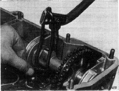
1 Press off spring clamps with a screwdriver.
|
|||
|
|
|||
|
2 Turn crankshaft with combination tool until cam peak is up.
Never turn engine on camshafts.
|
 |
||
|
|
|||
|
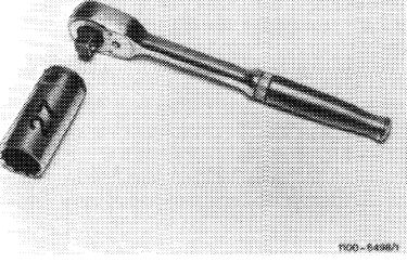
3 Remove rocker arms with installation and removal tool.
|
 |
||
|
|
|||
|
05.2-230/2 F3
|
|||
|
|
|||
|
|
|||
|
Installation
|
 |
||
|
4 Check oil spray bore in rocker arm for plugging.
5 Coat bearing surfaces of rocker arm with oil and install rocker arm.
6 Press spring clamps into grooves of adjusting screws.
7 Adjust valve clearance (05—210).
|
|||
|
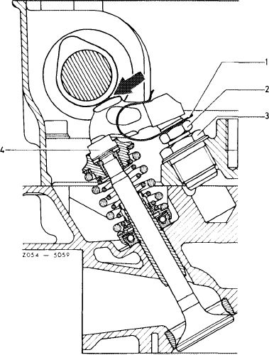
1 Spring clamp
2 Adjusting screw
3 Threaded bushing
4 Pressure pad
|
|||
|
|
|||
|
05.2-230/3
|
|||
|
|
|||