Removal and installation of valve springs
|
|
||||||||||||||||||||||||||||||||||||||
|
05—250 Removal and installation of valve springs
|
||||||||||||||||||||||||||||||||||||||
|
|
||||||||||||||||||||||||||||||||||||||
|
Valve clearance
|
Cold engine (ca. 20 °C)
|
Warm engine (60 °C ± 15°C)
|
||||||||||||||||||||||||||||||||||||
|
|
||||||||||||||||||||||||||||||||||||||
|
Intake
|
0.101
|
0.151
|
||||||||||||||||||||||||||||||||||||
|
|
||||||||||||||||||||||||||||||||||||||
|
Exhaust
|
0.25
|
0.30
|
||||||||||||||||||||||||||||||||||||
|
|
||||||||||||||||||||||||||||||||||||||
|
0.05 mm more for consistent outside temperatures below —20 °C.
|
||||||||||||||||||||||||||||||||||||||
|
|
||||||||||||||||||||||||||||||||||||||
|
Tightening torques
|
Nm
|
|||||||||||||||||||||||||||||||||||||
|
|
||||||||||||||||||||||||||||||||||||||
|
||||||||||||||||||||||||||||||||||||||
|
|
||||||||||||||||||||||||||||||||||||||
|
Rail to hold down valve springs
|
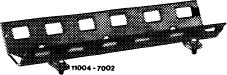 |
110 589 06 62 00
|
||||||||||||||||||||||||||||||||||||
| https://mbci.mackuz.ovh/
|
||||||||||||||||||||||||||||||||||||||
|
Magnetic lifter for valve collets
|
 |
116 589 06 63 00
|
||||||||||||||||||||||||||||||||||||
|
|
||||||||||||||||||||||||||||||||||||||
|
Depressor for valve spring
|
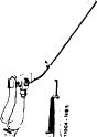 |
110 589 04 61 00
|
||||||||||||||||||||||||||||||||||||
|
|
||||||||||||||||||||||||||||||||||||||
|
Chain tensioner holder
|
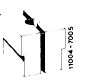 |
110 589 02 31 00
|
||||||||||||||||||||||||||||||||||||
|
|
||||||||||||||||||||||||||||||||||||||
|
Impact extractor for bearing pin (basic unit)
|
 |
116 589 20 33 00
|
||||||||||||||||||||||||||||||||||||
|
|
||||||||||||||||||||||||||||||||||||||
|
M 6 x 50 bolt for impact extractor
|
116 589 01 34 00
|
|||||||||||||||||||||||||||||||||||||
|
|
||||||||||||||||||||||||||||||||||||||
|
Valve adjusting wrench 17 mm, 1/2″ square
|
 |
110 589 00 01 00
|
||||||||||||||||||||||||||||||||||||
|
|
||||||||||||||||||||||||||||||||||||||
|
Wrench socket 27 mm, 1/2″ square to turn engine
|
 |
001 589 65 09 00
|
||||||||||||||||||||||||||||||||||||
|
|
||||||||||||||||||||||||||||||||||||||
|
05.2-250/1 F3
|
||||||||||||||||||||||||||||||||||||||
|
|
||||||||||||||||||||||||||||||||||||||

|
|
||||||||||||||||||||||||||||||||
|
||||||||||||||||||||||||||||||||
|
|
||||||||||||||||||||||||||||||||
 |
||||||||||||||||||||||||||||||||
|
|
||||||||||||||||||||||||||||||||
|
Removal
|
||||||||||||||||||||||||||||||||
|
|
||||||||||||||||||||||||||||||||
|
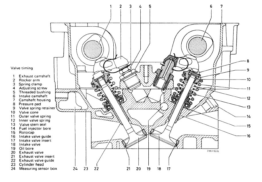
1 Remove camshaft housing (01—470).
2 Remove pressure pads (8).
3 Unscrew spark plug of respective cylinder and set piston to ignition TDC to prevent valves from dropping in.
|
||||||||||||||||||||||||||||||||
|
|
||||||||||||||||||||||||||||||||
|
05.2-250/2 F3
|
||||||||||||||||||||||||||||||||
|
|
||||||||||||||||||||||||||||||||
|
|
|||||||||||||||||||||||||||||||||||||||||||||||||||
|
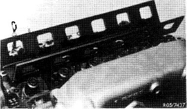
4 Bolt hold-down rail to cylinder head.
|
|||||||||||||||||||||||||||||||||||||||||||||||||||
|
|
|||||||||||||||||||||||||||||||||||||||||||||||||||
|
5 Support valves with pneumatic air (cylinder leak tester).
|
 |
||||||||||||||||||||||||||||||||||||||||||||||||||
|
|
|||||||||||||||||||||||||||||||||||||||||||||||||||
|
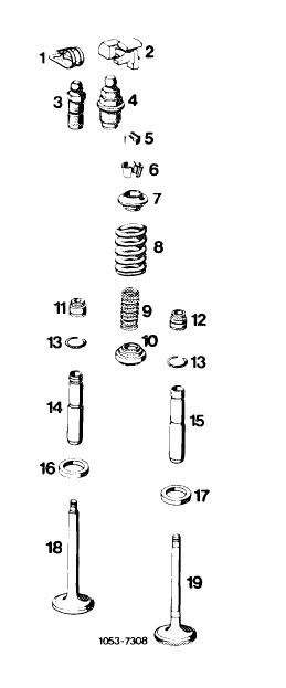
6 Loosen valve collets by applying light knocks from a hammer to valve spring retainers.
7 Press down valve spring retainer with removal and installation tool and remove valve collets with magnetic lifter.
Attention!
Valves must not rest on piston skirt, since this could bend the valves.
8 Remove valve spring retainer, outer and inner valve springs.
|
 |
||||||||||||||||||||||||||||||||||||||||||||||||||
|
|
|||||||||||||||||||||||||||||||||||||||||||||||||||
|
Installation
|
|||||||||||||||||||||||||||||||||||||||||||||||||||
|
|
|||||||||||||||||||||||||||||||||||||||||||||||||||
|
9 Check valve springs and replace if necessary (05— 260).
10 Replace valve stem seals (05-270).
11 Further installation in reverse sequence of removal.
Attention!
Install valve springs that tighter coil ends rest on roto-cap.
|
 |
||||||||||||||||||||||||||||||||||||||||||||||||||
|
Valves and rocker arms
|
|||||||||||||||||||||||||||||||||||||||||||||||||||
|
|||||||||||||||||||||||||||||||||||||||||||||||||||
|
|
|||||||||||||||||||||||||||||||||||||||||||||||||||
|
05.2-250/3 F2
|
|||||||||||||||||||||||||||||||||||||||||||||||||||
|
|
|||||||||||||||||||||||||||||||||||||||||||||||||||