Removal and installation of camshafts
|
|
||||||||||||||||||||||||||||||||||||||||||||||||||||||||||||||||||||||||||||||||||||||||||||||||||||||
|
05—220 Removal and installation of camshafts
|
||||||||||||||||||||||||||||||||||||||||||||||||||||||||||||||||||||||||||||||||||||||||||||||||||||||
|
|
||||||||||||||||||||||||||||||||||||||||||||||||||||||||||||||||||||||||||||||||||||||||||||||||||||||
|
||||||||||||||||||||||||||||||||||||||||||||||||||||||||||||||||||||||||||||||||||||||||||||||||||||||
|
|
||||||||||||||||||||||||||||||||||||||||||||||||||||||||||||||||||||||||||||||||||||||||||||||||||||||
|
’) Camshaft codes are stamped on rear end of camshaft.
|
||||||||||||||||||||||||||||||||||||||||||||||||||||||||||||||||||||||||||||||||||||||||||||||||||||||
|
|
||||||||||||||||||||||||||||||||||||||||||||||||||||||||||||||||||||||||||||||||||||||||||||||||||||||
|
Valve clearance
|
Cold engine (approx. 20
|
Warm engine (60 °C ± 15
|
||||||||||||||||||||||||||||||||||||||||||||||||||||||||||||||||||||||||||||||||||||||||||||||||||||
|
|
||||||||||||||||||||||||||||||||||||||||||||||||||||||||||||||||||||||||||||||||||||||||||||||||||||||
|
Intake
|
0.101
|
0.151)
|
||||||||||||||||||||||||||||||||||||||||||||||||||||||||||||||||||||||||||||||||||||||||||||||||||||
|
|
||||||||||||||||||||||||||||||||||||||||||||||||||||||||||||||||||||||||||||||||||||||||||||||||||||||
|
Exhaust
|
0.25
|
0.30
|
||||||||||||||||||||||||||||||||||||||||||||||||||||||||||||||||||||||||||||||||||||||||||||||||||||
|
|
||||||||||||||||||||||||||||||||||||||||||||||||||||||||||||||||||||||||||||||||||||||||||||||||||||||
|
M 0.05 mm more for consistent outside temperatures below —20 °C.
|
||||||||||||||||||||||||||||||||||||||||||||||||||||||||||||||||||||||||||||||||||||||||||||||||||||||
|
|
||||||||||||||||||||||||||||||||||||||||||||||||||||||||||||||||||||||||||||||||||||||||||||||||||||||
|
Data
|
||||||||||||||||||||||||||||||||||||||||||||||||||||||||||||||||||||||||||||||||||||||||||||||||||||||
|
|
||||||||||||||||||||||||||||||||||||||||||||||||||||||||||||||||||||||||||||||||||||||||||||||||||||||
|
Permissible runout of center bearing journal and camshaft sprocket seat when camshaft turns on outer bearing journals
|
0.025
|
|||||||||||||||||||||||||||||||||||||||||||||||||||||||||||||||||||||||||||||||||||||||||||||||||||||
|
|
||||||||||||||||||||||||||||||||||||||||||||||||||||||||||||||||||||||||||||||||||||||||||||||||||||||
|
Scleroscope hardness of cams
|
68-82
|
|||||||||||||||||||||||||||||||||||||||||||||||||||||||||||||||||||||||||||||||||||||||||||||||||||||
|
|
||||||||||||||||||||||||||||||||||||||||||||||||||||||||||||||||||||||||||||||||||||||||||||||||||||||
|
Special tools
|
||||||||||||||||||||||||||||||||||||||||||||||||||||||||||||||||||||||||||||||||||||||||||||||||||||||
|
|
||||||||||||||||||||||||||||||||||||||||||||||||||||||||||||||||||||||||||||||||||||||||||||||||||||||
|
Depressor for valve spring
|
 |
110 589 04 61 00
|
||||||||||||||||||||||||||||||||||||||||||||||||||||||||||||||||||||||||||||||||||||||||||||||||||||
|
|
||||||||||||||||||||||||||||||||||||||||||||||||||||||||||||||||||||||||||||||||||||||||||||||||||||||
|
Rigid chain tensioner
|
 |
110 589 03 31 00
|
||||||||||||||||||||||||||||||||||||||||||||||||||||||||||||||||||||||||||||||||||||||||||||||||||||
|
|
||||||||||||||||||||||||||||||||||||||||||||||||||||||||||||||||||||||||||||||||||||||||||||||||||||||
|
Chain tensioner holder
|
 |
110 589 02 31 00
|
||||||||||||||||||||||||||||||||||||||||||||||||||||||||||||||||||||||||||||||||||||||||||||||||||||
|
|
||||||||||||||||||||||||||||||||||||||||||||||||||||||||||||||||||||||||||||||||||||||||||||||||||||||
|
05.2-220/1 F3
|
||||||||||||||||||||||||||||||||||||||||||||||||||||||||||||||||||||||||||||||||||||||||||||||||||||||
|
|
||||||||||||||||||||||||||||||||||||||||||||||||||||||||||||||||||||||||||||||||||||||||||||||||||||||
|
|
|||||||||||||||||||||||||||||||||||||||||||||||||
|
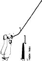
Camshaft holding wrench
|
 |
116 589 01 01 00
|
|||||||||||||||||||||||||||||||||||||||||||||||
|
|
|||||||||||||||||||||||||||||||||||||||||||||||||
|
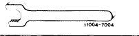
Valve adjusting wrench 17 mm
|
 |
110 589 01 01 00
|
|||||||||||||||||||||||||||||||||||||||||||||||
|
11004-7003
|
|||||||||||||||||||||||||||||||||||||||||||||||||
|
|
|||||||||||||||||||||||||||||||||||||||||||||||||
|
|||||||||||||||||||||||||||||||||||||||||||||||||
|
|
|||||||||||||||||||||||||||||||||||||||||||||||||
|
Impact extractor for bearing pin (basic unit)
|
 |
116 589 20 33 00
|
|||||||||||||||||||||||||||||||||||||||||||||||
|
|
|||||||||||||||||||||||||||||||||||||||||||||||||
|
|||||||||||||||||||||||||||||||||||||||||||||||||
|
|
|||||||||||||||||||||||||||||||||||||||||||||||||
|
Note
|
|||||||||||||||||||||||||||||||||||||||||||||||||
|
|
|||||||||||||||||||||||||||||||||||||||||||||||||
|
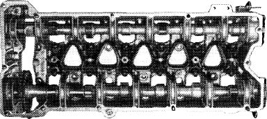
Camshafts can be removed from an installed engine only together with the camshaft housing.
If a new camshaft has to be installed, the rocker arms must also be replaced.
|
 |
||||||||||||||||||||||||||||||||||||||||||||||||
|
|
|||||||||||||||||||||||||||||||||||||||||||||||||
|
105-8003
|
|||||||||||||||||||||||||||||||||||||||||||||||||
|
|
|||||||||||||||||||||||||||||||||||||||||||||||||
|
05.2-220/2 F3
|
|||||||||||||||||||||||||||||||||||||||||||||||||
|
|
|||||||||||||||||||||||||||||||||||||||||||||||||
|
|
||||
|
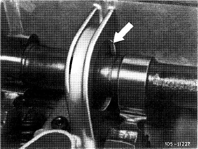
Camshafts with wide bearing journals (e.g. 21 mm) can be exchanged against camshafts with narrow bearing journals (arrow) (e.g. 16 mm).
Attention!
Exchange engines are partially delivered with camshaft bearing journals ground to intermediate or repair stage dimension (01—471).
Install camshafts with reground bearing journals in a camshaft housing with a pertinent bearing diameter (05-225).
Also refer to coordination camshaft housing and camshafts (01-471).
|
 |
|||
|
|
||||
|
Removal
|
||||
|
|
||||
|
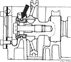
1 Remove camshaft housing (01—470).
2 Unscrew both rear covers on camshafts housing.
3 Unscrew necked-down screw of lefthand camshaft while applying counterhold with holding wrench.
|
 |
|||
|
|
||||
|
505-8003
|
||||
|
|
||||
|
4 Press back camshafts and remove camshaft sprocket.
|
||||
|
|
||||
|
5 Remove both camshafts toward rear.
|
||||
|
|
||||
|
Installation
|
 |
|||
|
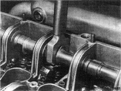
6 Coat camshaft bearings with engine oil and guide in left camshaft (intake). Slide on camshaft sprocket (6) and spacer (5). Coat spacer (3) with engine oil and install.
|
||||
|
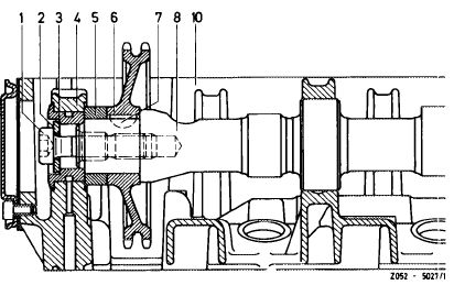
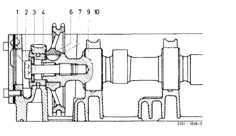
Intake camshaft
1 Expansion bolt
2 Washer
3 Spacer
4 Bearing
5 Spacer
|
6 Camshaft sprocket
7 Woodruff key
8 Camshaft
10 Camshaft housing
|
|||
|
|
||||
|
05.2-220/3 F3
|
||||
|
|
||||
|
|
||||
|
7 Expansion bolt (3) with washer (2) must be installed for repair jobs. Mounting bolt (9) and spring washers (8) must not be used.
|
 |
|||
|
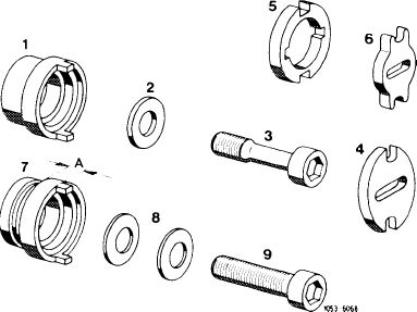
1 Spacer 2nd version without lubricating groove (for pressure oil pump and vacuum pump 2nd version)
2 Washer
3 Expansion bolt
4 Dog (for pressure oil pump and vacuum pump 2nd version)
5 Dog (for vacuum pump 1st version)
6 Dog 1st version (for pressure oil pump)
7 Spacer 1st version with lubricating groove A = 4.7 mm for vacuum pump 1st version
A = 8.3 mm for pressure oil pump and vacuum pump 2nd version
8 Spring washers (not valid)
9 Mounting bolt (not valid)
|
||||
|
|
||||
|
Note: Lubricating groove in spacing sleeve (arrow) no longer in place starting January 1974.
|
 |
|||
|
|
||||
|
8 Tighten torque camshaft expansion bolt to 80 Nm (8 kpm), counterholding camshaft with a holding wrench.
|
 |
|||
|
|
||||
|
9 Guide right camshaft (exhaust) into lubricated bearings.
The right camshaft sprocket is installed after the camshaft housing has been mounted.
|
 |
|||
|
Exhaust camshaft
1 Expansion bolt
2 Washer
3 Spacer
4 Bearing
|
6 Camshaft sprocket
7 Woodruff key 9 Camshaft
10 Camshaft housing
|
|||
|
|
||||
|
05.2-220/4 F3
|
||||
|
|
||||
|
|
|||
|
10 Install both rear covers with gaskets on camshaft housing.
11 Install camshaft housing (01—470).
|
 |
||
|
|
|||
|
05.2-220/5 F3
|
|||
|
|
|||