Checking and adjusting camshaft timing
|
|
|||||||||||||||||||||||||||||||||||||||||||||||||||||||||||||||||||||||||||||||||||||||||||||||||||||||
|
05—215 Checking and adjusting camshaft timing
|
|||||||||||||||||||||||||||||||||||||||||||||||||||||||||||||||||||||||||||||||||||||||||||||||||||||||
|
|
|||||||||||||||||||||||||||||||||||||||||||||||||||||||||||||||||||||||||||||||||||||||||||||||||||||||
|
|||||||||||||||||||||||||||||||||||||||||||||||||||||||||||||||||||||||||||||||||||||||||||||||||||||||
|
|
|||||||||||||||||||||||||||||||||||||||||||||||||||||||||||||||||||||||||||||||||||||||||||||||||||||||
|
’) Camshaft code number is punched into rear end of camshaft.
|
|||||||||||||||||||||||||||||||||||||||||||||||||||||||||||||||||||||||||||||||||||||||||||||||||||||||
|
|
|||||||||||||||||||||||||||||||||||||||||||||||||||||||||||||||||||||||||||||||||||||||||||||||||||||||
|
Valve clearance
|
On cold engine (approx. 20 °C)
|
On warm engine (60 C±15 C)
|
|||||||||||||||||||||||||||||||||||||||||||||||||||||||||||||||||||||||||||||||||||||||||||||||||||||
|
|
|||||||||||||||||||||||||||||||||||||||||||||||||||||||||||||||||||||||||||||||||||||||||||||||||||||||
|
Intake
|
0.101)
|
0.151)
|
|||||||||||||||||||||||||||||||||||||||||||||||||||||||||||||||||||||||||||||||||||||||||||||||||||||
|
|
|||||||||||||||||||||||||||||||||||||||||||||||||||||||||||||||||||||||||||||||||||||||||||||||||||||||
|
Exhaust
|
0.25
|
0.30
|
|||||||||||||||||||||||||||||||||||||||||||||||||||||||||||||||||||||||||||||||||||||||||||||||||||||
|
|
|||||||||||||||||||||||||||||||||||||||||||||||||||||||||||||||||||||||||||||||||||||||||||||||||||||||
|
’) 0.05 mm larger during lasting outside temperatures below —20 °C.
|
|||||||||||||||||||||||||||||||||||||||||||||||||||||||||||||||||||||||||||||||||||||||||||||||||||||||
|
|
|||||||||||||||||||||||||||||||||||||||||||||||||||||||||||||||||||||||||||||||||||||||||||||||||||||||
|
|||||||||||||||||||||||||||||||||||||||||||||||||||||||||||||||||||||||||||||||||||||||||||||||||||||||
|
|
|||||||||||||||||||||||||||||||||||||||||||||||||||||||||||||||||||||||||||||||||||||||||||||||||||||||
|
Depressor for valve springs
|
 |
110 589 04 61 00
|
|||||||||||||||||||||||||||||||||||||||||||||||||||||||||||||||||||||||||||||||||||||||||||||||||||||
|
|
|||||||||||||||||||||||||||||||||||||||||||||||||||||||||||||||||||||||||||||||||||||||||||||||||||||||
|
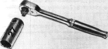
Socket 27 mm, 1/2″ square for rotating engine
|
001 589 65 09 00
|
||||||||||||||||||||||||||||||||||||||||||||||||||||||||||||||||||||||||||||||||||||||||||||||||||||||
|
|
|||||||||||||||||||||||||||||||||||||||||||||||||||||||||||||||||||||||||||||||||||||||||||||||||||||||
|
Impact extractor for bearing pins (Basic unit)
|
 |
116 589 20 33 00
|
|||||||||||||||||||||||||||||||||||||||||||||||||||||||||||||||||||||||||||||||||||||||||||||||||||||
|
|
|||||||||||||||||||||||||||||||||||||||||||||||||||||||||||||||||||||||||||||||||||||||||||||||||||||||
|
M 6 x 50 bolt for impact extractor
|
 |
116 589 01 34 00
|
|||||||||||||||||||||||||||||||||||||||||||||||||||||||||||||||||||||||||||||||||||||||||||||||||||||
|
|
|||||||||||||||||||||||||||||||||||||||||||||||||||||||||||||||||||||||||||||||||||||||||||||||||||||||
|
05.2-215/1 F3
|
|||||||||||||||||||||||||||||||||||||||||||||||||||||||||||||||||||||||||||||||||||||||||||||||||||||||
|
|
|||||||||||||||||||||||||||||||||||||||||||||||||||||||||||||||||||||||||||||||||||||||||||||||||||||||
|
|
||||||||||||||||||||||||||||||||||||||||
|
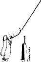
Timing test tool
|
 |
110 589 10 21 00
|
||||||||||||||||||||||||||||||||||||||
|
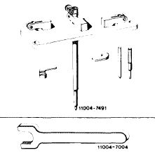
Camshaft holding wrench
|
116 589 01 01 00
|
|||||||||||||||||||||||||||||||||||||||
|
|
||||||||||||||||||||||||||||||||||||||||
|
Valve adjusting wrench 17 mm
|
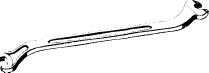 |
110 589 01 01 00
|
||||||||||||||||||||||||||||||||||||||
|
11004-7003
|
||||||||||||||||||||||||||||||||||||||||
|
|
||||||||||||||||||||||||||||||||||||||||
|
Holding jaws for chain tensioner
|
 |
110 589 02 31 00
|
||||||||||||||||||||||||||||||||||||||
|
|
||||||||||||||||||||||||||||||||||||||||
|
||||||||||||||||||||||||||||||||||||||||
|
|
||||||||||||||||||||||||||||||||||||||||
|
Note
|
 |
|||||||||||||||||||||||||||||||||||||||
|
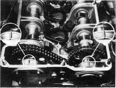
Check when intake valve begins to open and exhaust valve of 1st cylinder stops to close.
For assembly jobs it is sufficient when the marks on the camshafts are aligned for ignition TDC position of 1st cylinder.
|
||||||||||||||||||||||||||||||||||||||||
|
|
||||||||||||||||||||||||||||||||||||||||
|
Checking
|
 |
|||||||||||||||||||||||||||||||||||||||
|
1 Remove both rocker arms of 1st cylinder with the installation and removal tool.
This requires turning the crankshaft until the cam peak is up.
|
||||||||||||||||||||||||||||||||||||||||
|
|
||||||||||||||||||||||||||||||||||||||||
|
05.2-215/2 F3
|
||||||||||||||||||||||||||||||||||||||||
|
|
||||||||||||||||||||||||||||||||||||||||
|
|
|||
|
Turn crankshaft with combination tool.
|
|||
|
|
|||
|
Attention!
Never turn engine on camshafts.
|
 |
||
|
|
|||
|
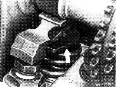
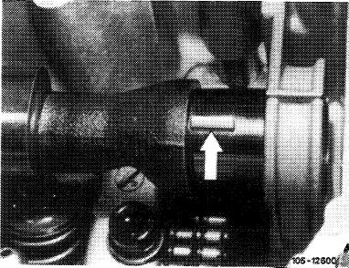
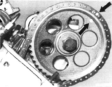
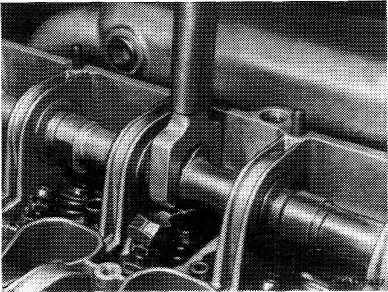
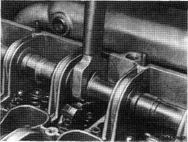
2 Replace both pressure pads by test pads (arrow) and install rocker arms without spring clamps.
|
 |
||
|
|
|||
|
3 Turn valve adjusting screw until rocker arm rests free of play against cam base circle.
|
 |
||
|
|
|||
|
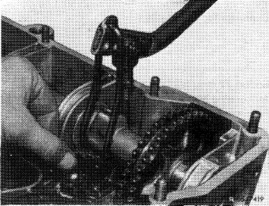
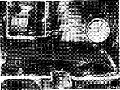
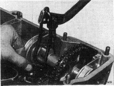
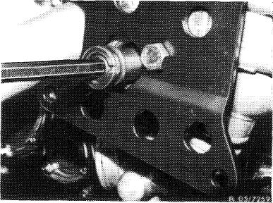
4 Set up and install tester.
5 When valve is closed, i. e. the cam faces up, insert the dial gage with an extension pin into the tester. Adjust for a preload of 3 mm (small indicator must point to 3) and clamp the dial gage.
Turn the adjustable dial, until the large indicator points to „0”.
|
 |
||
|
|
|||
|
05.2-215/3 F3
|
|||
|
|
|||
|
|
|||
|
Checking opening of intake valve
6 Continue turning crankshaft in engine’s direction of rotation (cam begins to open valve), until the dial gage goes back by 2 mm (valve stroke) to a preload of 1 mm.
The value on the vibration damper must correspond with the specified value for „intake valve opens after TDC” in this engine position.
|
|||
|
|
|||
|
Checking closing of exhaust valve
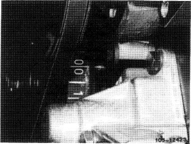
7 Continue turning crankshaft in engine’s direction of rotation. The exhaust valve will be opened and the dial gage returns to „0”. Now when closing the exhaust valve, the dial gage pin returns to position and the indicators begin to turn. The small indicator must stop at 1 and the large indicator at „0”.
|
|||
|
|
|||
|
The value on the vibration damper must correspond with the specified value for „exhaust valve closes before TDC” in this engine position.
|
 |
||
|
|
|||
|
Adjusting
|
 |
||
|
If the timing has to be corrected, an offset woodruff key or a new timing chain, if chain stretching is excessive, must be installed.
|
|||
|
|
|||
|
05.2-215/4
|
|||
|
|
|||
|
|
||||||||||||||||||||||||||||||||||||||||||||||||||||||||||
|
Woodruff keys are available in the following sizes.
|
 |
|||||||||||||||||||||||||||||||||||||||||||||||||||||||||
|
||||||||||||||||||||||||||||||||||||||||||||||||||||||||||
|
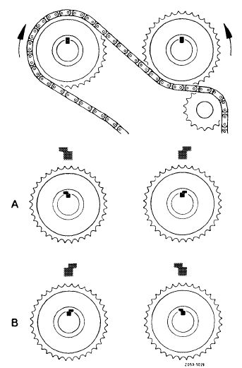
An offset of 1 tooth on the camshaft sprocket means about 18° on the crankshaft.
|
||||||||||||||||||||||||||||||||||||||||||||||||||||||||||
|
Since both camshafts rotate against each other, the installed position is important when installing an offset woodruff key.
|
||||||||||||||||||||||||||||||||||||||||||||||||||||||||||
|
|
||||||||||||||||||||||||||||||||||||||||||||||||||||||||||
|
With installed position „A” opening begins earlier With installed position „B” opening begins later
|
||||||||||||||||||||||||||||||||||||||||||||||||||||||||||
|
|
||||||||||||||||||||||||||||||||||||||||||||||||||||||||||
|
8 Remove all rocker arms on camshaft to be adjusted (05-230).
|
 |
|||||||||||||||||||||||||||||||||||||||||||||||||||||||||
|
|
||||||||||||||||||||||||||||||||||||||||||||||||||||||||||
|
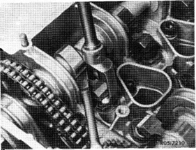
9 Set first cylinder of engine at ignition TDC. Marks on camshaft sprockets and camshaft housing must align.
|
 |
|||||||||||||||||||||||||||||||||||||||||||||||||||||||||
|
|
||||||||||||||||||||||||||||||||||||||||||||||||||||||||||
|
05.2-215/5
|
||||||||||||||||||||||||||||||||||||||||||||||||||||||||||
|
|
||||||||||||||||||||||||||||||||||||||||||||||||||||||||||
|
|
||||
|
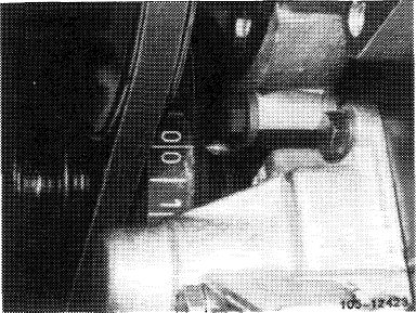
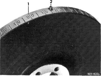
Attention!
If the vibration damper of an engine has a „0/0” mark for BDC in addition to one for TDC, the TDC mark is next to the pin in the vibration damper.
|
 |
|||
|
1 TDC mark
|
||||
|
|
||||
|
10 Mark relation between camshaft sprockets and chain with paint to facilitate assembly.
|
 |
|||
|
|
||||
|
11 Remove chain tensioner (05—310).
|
 |
|||
|
|
||||
|
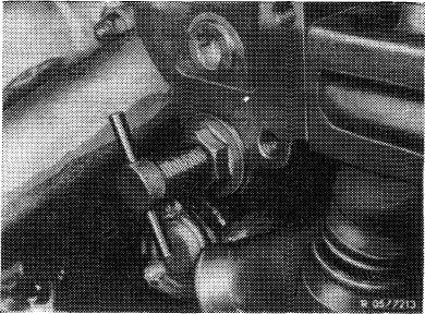
12 Knock out only the bottom bearing pin of the sliding rail in the camshaft housing with an impact extractor.
|
 |
|||
|
|
||||
|
05.2-215/6
|
||||
|
|
||||
|
|
||||
|
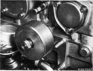
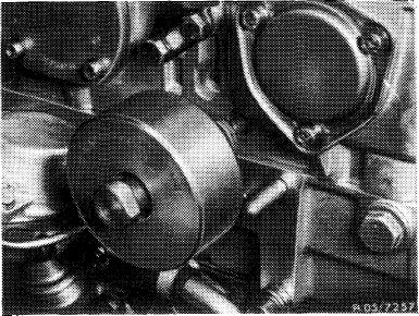
13 Remove expansion bolt for camshaft sprocket, counterholding camshaft with a holding wrench.
|
 |
|||
|
|
||||
|
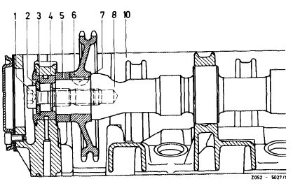
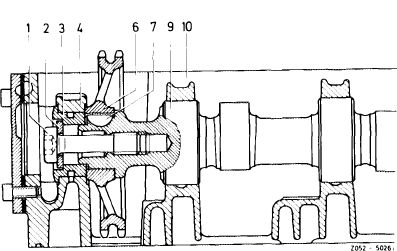
14 Press back camshaft and remove camshaft sprocket. Take spacer (5) off of intake camshaft.
|
 |
|||
|
Intake camshaft
1 Expansion bolt
2 Washer
3 Spacer
4 Bearing
5 Spacer
|
6 Camshaft sprocket
7 Woodruff key
8 Camshaft
10 Camshaft housing
|
|||
|
|
||||
|
15 Place a clean cloth in timing chain housing underneath the camshaft and remove the woodruff key.
16 Install a woodruff key (7) selected according to the diagram.
|
 |
|||
|
Exhaust camshaft
1 Expansion bolt
2 Washer
3 Spacer
4 Bearing
|
6 Camshaft sprocket
7 Woodruff key 9 Camshaft
10 Camshaft housing
|
|||
|
|
||||
|
17 Install camshaft sprocket and bottom sliding rail bearing pin, so that the timing chain cannot jump.
|
 |
|||
|
|
||||
|
05.2-215/7
|
||||
|
|
||||
|
|
|||
|
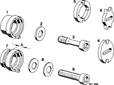
Note: Use only expansion bolt (3) with washer (2) for repairs.
|
 |
||
|
1 Spacer 2nd version without lubricating groove (for pressure oil pump and vacuum pump 2nd version)
2 Washer
3 Expansion bolt
4 Dog for pressure oil pump and vacuum pump 2nd version
5 Dog for vacuum pump 1st version
6 Dog 1st version for pressure oil pump
7 Spacer 1st version with lubricating groove A = 4.7 mm for vacuum pump 1st version
A = 8.3 mm for pressure oil pump and vacuum pump 2nd version
8 Spring washers (not valid)
9 Mounting bolt (not valid)
|
|||
|
|
|||
|
18 Install rigid chain tensioner and tension by hand.
|
 |
||
|
19 Turn crankshaft with combination tool.
|
|||
|
20 Check timing.
|
|||
|
|
|||
|
21 Torque expansion bolts for camshaft sprocket to 80 Nm (8 kpm), counterholding with a holding wrench.
|
 |
||
|
|
|||
|
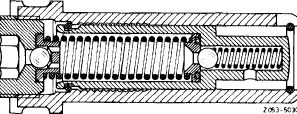
22 Position chain tensioner for installation and install (05-310).
23 Install rocker arms (05-230).
24 Adjust valve clearance (05-210).
|
 |
||
|
|
|||
|
Chain tensioner positioned for installation.
|
|||
|
|
|||
|
05.2-215/8
|
|||
|
|
|||