Checking and adjusting on-off ratio
|
|
||||||||||||||||||||||||||||||
|
07.3—105 Checking and adjusting on-off ratio
|
||||||||||||||||||||||||||||||
|
|
||||||||||||||||||||||||||||||
|
National version
|
||||||||||||||||||||||||||||||
|
|
||||||||||||||||||||||||||||||
|
Identification: Information label in national language on radiator cross member. Adjust engines according to data on respective emission label.
|
||||||||||||||||||||||||||||||
|
|
||||||||||||||||||||||||||||||
|
Testing and adjusting values
|
||||||||||||||||||||||||||||||
|
|
||||||||||||||||||||||||||||||
|
Model year
|
Idle speed 1/min On-off ratio in %
Test value
|
Adjusting value
|
||||||||||||||||||||||||||||
|
|
||||||||||||||||||||||||||||||
|
Identification: Label in Japanese language.
|
||||||||||||||||||||||||||||||
|
|
||||||||||||||||||||||||||||||
|
1981/82
|
750 ± 50
|
40-60
|
50 ± 10
|
|||||||||||||||||||||||||||
|
|
||||||||||||||||||||||||||||||
|
Identification: Label, black.
|
||||||||||||||||||||||||||||||
|
|
||||||||||||||||||||||||||||||
|
1980/81
|
750 ± 50
|
40-60
|
50 ± 10
|
|||||||||||||||||||||||||||
|
|
||||||||||||||||||||||||||||||
|
Special tools
|
||||||||||||||||||||||||||||||
|
|
||||||||||||||||||||||||||||||
|
Oil telethermometer
|
 |
116 589 27 21 00
|
||||||||||||||||||||||||||||
|
|
||||||||||||||||||||||||||||||
|
Puller for safety plug
|
123 589 05 33 00
|
|||||||||||||||||||||||||||||
|
|
||||||||||||||||||||||||||||||
|
Installer for safety plug
|
11004-8278
|
123 589 00 15 00
|
||||||||||||||||||||||||||||
|
|
||||||||||||||||||||||||||||||
|
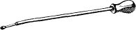
Screw driver 3 mm with tommy handle for readjusting idle speed emission value
|
 |
000 589 14 11 00
|
||||||||||||||||||||||||||||
|
|
||||||||||||||||||||||||||||||
|
||||||||||||||||||||||||||||||
|
|
||||||||||||||||||||||||||||||
|
07.3.2 Ha—105/1 F2
|
||||||||||||||||||||||||||||||
|
|
||||||||||||||||||||||||||||||
|
|
|||
|
Adjustment
|
|||
|
|
|||
|
1 Connect digital tester or revolution counter, oil telethermometer and lambda control tester.
2 Switch off air conditioning or automatic climate control. Move selector lever into position „P”.
3 Run engine to 75-85 °C.
4 Check whether throttle valve lever rests against idle speed stop.
|
|||
|
|
|||
|
5 Check intake system for leaks. For this purpose, spray all sealing points with Iso-Oktan DIN 51756 or benzine.
Attention!
Do not use conventional fuel for spraying (unhealthy vapors). Pay attention to inflammability and do not spray on red-hot parts or components of ignition system.
|
|||
|
|
|||
|
6 Vehicles with cruise control/tempomat:
|
 |
||
|
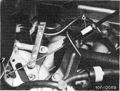
Cruise control/tempomat, pneumatic
Check whether bowden wire for cruise control/tempomat rests free of tension against regulating lever (7). Adjust with adjusting nut (6), if required.
|
|||
|
|
|||
|
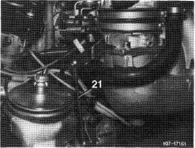
Cruise control/tempomat, electrical
Check whether actuator rests against idle speed stop of cruise control/tempomat. For this purpose, disconnect pull rod (21) and push lever of actuator clockwise to idle speed stop.
When connecting pull rod (21), make sure that lever of the actuator is raised by approx. 1 mm from idle speed stop. Adjust pull rod, if required.
|
 |
||
|
|
|||
|
07.3.2 lla-105/2 F2
|
|||
|
|
|||
|
|
||||
|
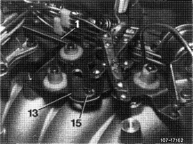
7 Check whether roller (15) in slotted lever (13) rests free of tension against final stop. Adjust with connecting rod (1), if required.
|
 |
|||
|
|
||||
|
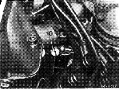
8 Run engine at idle, switch off all electrical auxiliary consumers. Adjust an idle speed of 750—50/min by means of idle speed air screw (10).
|
 |
|||
|
|
||||
|
9 Check on-off ratio and adjust, if required. (T) starting 1981, (JJSa)1980.
Note: Air cleaner need not be removed for adjusting on-off ratio at idle.
|
||||
|
|
||||
|
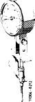
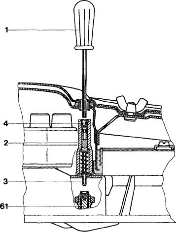
Read on-off ratio on tester, if value is between 40—60 %, on-off ratio is in order. If not, pull out safety plug (4) by means of puller.
Insert screw driver (1) through cutout in air cleaner top and push against adjusting device (2). Push adjusting device down by means of screw driver against force of spring, turn slightly until hexagon (3) enters mixture control screw (61).
Turning counterclockwise = 60 % (leaner) Turning clockwise = 40 % (richer)
|
 |
1073-8838
|
||
|
|
||||
|
07.3.2 lla-105/3 F2
|
||||
|
|
||||
|
|
||||
|
Release screw driver, compression spring will push adjusting device out of mixture control screw.
Accelerate for a short moment, check on-off ratio and readjust, if required.
Following adjustment, install a blue safety plug (4), part no. 000 997 56 86 by means of installer.
|
||||
|
|
||||
|
1981
|
 |
1073-10585
|
||
|
Note
|
||||
|
The adjusting device (2) is provided with a protective steel cap (4). Remove this cap only in the event of repairs, e.g. when renewing fuel distributor.
Read on-off ratio on tester, if value is between 40— 60 %, on-off ratio is in order. If not, remove air cleaner.
Punch mark protective cap (4) and drill through sleeve with a 2 mm twist drill.
Screw 2.5 mm sheet metal screw (cut off tip) into hole and pull out protective cap (4) by means of pliers.
Push with screw driver (1) against adjusting device (2). Push adjusting device down with screw driver against force of spring, turn slightly until hexagon (3) enters mixture control screw (61).
Turning counterclockwise = 60 % (leaner) Turning clockwise = 40 % (richer)
Release screw driver, compression spring will then push adjusting device out of mixture control screw.
Mount air cleaner, accelerate for a short moment, check on-off ratio and readjust, if required.
Following adjustment, install new protective cap (4), part no. 116 070 00 54.
10 Move selector lever into driving position, switch on air conditioning, turn power steering to full lock, engine should now run smoothly. Readjust speed, if required.
|
||||
|
|
||||
|
07.3.2 lla-105/4 F2
|
||||
|
|
||||