Mounting of crankshaft
|
|
||||||||||||||||||||||||||||||||||||||||||||||||||||||||
|
03-320 Mounting of crankshaft
|
||||||||||||||||||||||||||||||||||||||||||||||||||||||||
|
|
||||||||||||||||||||||||||||||||||||||||||||||||||||||||
|
Data
|
||||||||||||||||||||||||||||||||||||||||||||||||||||||||
|
|
||||||||||||||||||||||||||||||||||||||||||||||||||||||||
|
||||||||||||||||||||||||||||||||||||||||||||||||||||||||
|
|
||||||||||||||||||||||||||||||||||||||||||||||||||||||||
|
||||||||||||||||||||||||||||||||||||||||||||||||||||||||
|
|
||||||||||||||||||||||||||||||||||||||||||||||||||||||||
|
when new
|
0.031 to 0.0531)
|
0.025 to 0.0651
|
||||||||||||||||||||||||||||||||||||||||||||||||||||||
|
|
||||||||||||||||||||||||||||||||||||||||||||||||||||||||
|
Radial bearing play
|
||||||||||||||||||||||||||||||||||||||||||||||||||||||||
|
|
||||||||||||||||||||||||||||||||||||||||||||||||||||||||
|
wear limit
|
0.08
|
|||||||||||||||||||||||||||||||||||||||||||||||||||||||
|
|
||||||||||||||||||||||||||||||||||||||||||||||||||||||||
|
when new
|
0.10-0.24
|
0.11-0.23
|
||||||||||||||||||||||||||||||||||||||||||||||||||||||
|
|
||||||||||||||||||||||||||||||||||||||||||||||||||||||||
|
Axial bearing play
|
||||||||||||||||||||||||||||||||||||||||||||||||||||||||
|
|
||||||||||||||||||||||||||||||||||||||||||||||||||||||||
|
wear limit
|
0.30
|
0.50
|
||||||||||||||||||||||||||||||||||||||||||||||||||||||
|
|
||||||||||||||||||||||||||||||||||||||||||||||||||||||||
|
||||||||||||||||||||||||||||||||||||||||||||||||||||||||
|
|
||||||||||||||||||||||||||||||||||||||||||||||||||||||||
|
1st repair stage 2nd repair stage 3rd repair stage 4th repair stage
|
3.625-3.638 3.750-3.763 3.875-3.888 4.000-4.013
|
29.4-29.63)
|
1.929-1.939 2.054-2.064 2.179-2.189 2.304-2.314
|
|||||||||||||||||||||||||||||||||||||||||||||||||||||
|
|
||||||||||||||||||||||||||||||||||||||||||||||||||||||||
|
1) Measured at apex of bearing shell.
2) The fitted bearing shells for 1st to 4th repair stage are supplied in oversize width and should be refinished in accordance with ground crankshaft bearing journal.
|
||||||||||||||||||||||||||||||||||||||||||||||||||||||||
|
|
||||||||||||||||||||||||||||||||||||||||||||||||||||||||
|
03.2-320/1 F 3
|
||||||||||||||||||||||||||||||||||||||||||||||||||||||||
|
|
||||||||||||||||||||||||||||||||||||||||||||||||||||||||
|
|
|||||||||||||||||||||||||||||||||||||||
|
Tightening torques
|
Nm
|
||||||||||||||||||||||||||||||||||||||
|
|
|||||||||||||||||||||||||||||||||||||||
|
Crankshaft bearing bolts
|
80
|
||||||||||||||||||||||||||||||||||||||
|
|
|||||||||||||||||||||||||||||||||||||||
|
initial torque
|
40-50
|
||||||||||||||||||||||||||||||||||||||
|
Connecting rod nuts
|
|||||||||||||||||||||||||||||||||||||||
|
|
|||||||||||||||||||||||||||||||||||||||
|
|||||||||||||||||||||||||||||||||||||||
|
|
|||||||||||||||||||||||||||||||||||||||
|
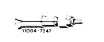
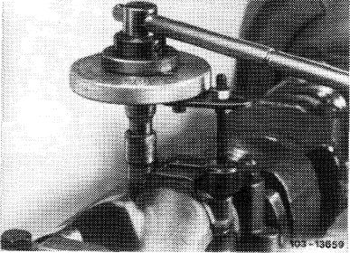
Puller for balancing disc
|
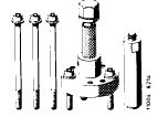 |
116 589 10 33 00
|
|||||||||||||||||||||||||||||||||||||
|
|
|||||||||||||||||||||||||||||||||||||||
|
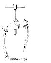
Puller for crankshaft gear
|
 |
615 5? 9 01 33 00
|
|||||||||||||||||||||||||||||||||||||
|
|
|||||||||||||||||||||||||||||||||||||||
|
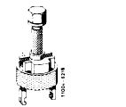
Detent
|
 |
110 589 00 40 00
|
|||||||||||||||||||||||||||||||||||||
|
|
|||||||||||||||||||||||||||||||||||||||
|
Countersupport for internal puller
|
 |
000 589 33 33 00
|
|||||||||||||||||||||||||||||||||||||
|
|
|||||||||||||||||||||||||||||||||||||||
|
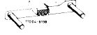
Internal puller 14.5—18.5 mm for radial ball bearing
|
 |
000 589 25 33 00
|
|||||||||||||||||||||||||||||||||||||
|
|
|||||||||||||||||||||||||||||||||||||||
|
Dial gauge holder for measuring end play
|
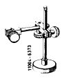 |
116 589 12 21 00
|
|||||||||||||||||||||||||||||||||||||
|
|
|||||||||||||||||||||||||||||||||||||||
|
03.2-320/2 F 3
|
|||||||||||||||||||||||||||||||||||||||
|
|
|||||||||||||||||||||||||||||||||||||||
|
|
|||
|
Note
Engine removed and disassembled.
Main oil duct in crankcase open (if with steel balls, refer to 01-130). Oil ducts in crankcase and in crankshaft carefully cleaned.
Test crankshaft for cracks, accuracy and hardness (03-318).
When grinding crankpins a difference of one repair stage only permitted per crankshaft.
|
|||
|
|
|||
|
Associating cranskhaft bearings, installing crankshaft
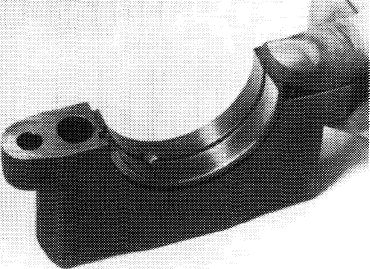
1 Install crankshaft bearing cap. Pay attention to identification, 1 is at front (arrows).
Do not mix up crankshaft bearing caps.
2 Tighten bolts to 80 Nm.
|
 |
||
|
|
|||
|
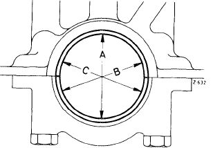
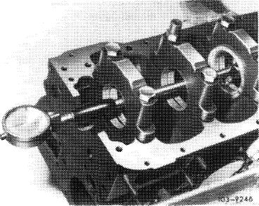
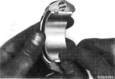
3 Measure basic bore in direction A, B and C in two levels (conicity).
If a basic bore exceeds the specified value or is conical, touch up bearing cap at its contact surface on a surface plate up to max. 0.02 mm.
|
 |
||
|
|
|||
|
4 Insert crankshaft bearing shells and mount bearing cap. Tighten bolts to 80 Nm torque.
Attention!
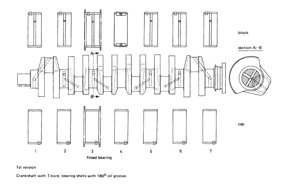
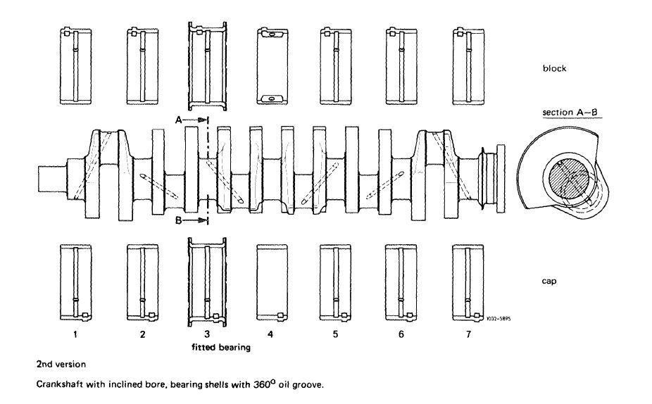
When associating crankshaft bearing shells, observe the two different crankshafts.
On crankshafts with tapered bore (2nd version) install crankshaft bearing shells with 360° oil groove.
|
 |
||
|
|
|||
|
1O3-13SS1
|
|||
|
|
|||
|
03.2-320/3 F 3
|
|||
|
|
|||
|
|
||
 |
||
|
|
||
 |
||
|
|
||
|
03.2-320/4 F2
|
||
|
|
||
|
|
|||
|
5 Measure bearing dia and write down.
|
 |
||
|
|
|||
|
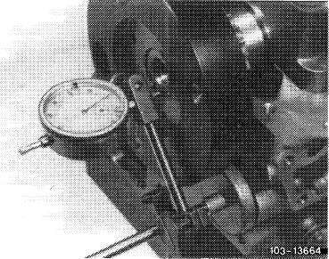
6 Measure crankshaft bearing journal, find radial crankshaft bearing play (vertical runout).
Note: The bearing play can be corrected by exchanging bearing shells, while trying for lower value (0.031 mm) of specified bearing play. Crankshaft bearing shells without color code are thicker than those with a blue color code, but the fact must be taken into consideration that a wall thickness without and one with color code may overlap.
|
 |
||
|
|
|||
|
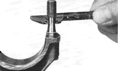
7 Measure width of fitted bearing journal and fitted bearing.
Measure crankshaft bearing end play.
Note: The fitted bearing shells of the repair stages are supplied at oversize.
Both fitted bearing shells must be machined on both sides down to width of fitted bearing journal minus end play. Try for lower value of 0.10 mm.
|
 |
||
|
|
|||
|
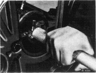
8 Replace rear crankshaft radial sealing ring (03-327).
9 Provide bearing shells, crankshaft and radial sealing ring with engine oil and install crankshaft.
|
 |
||
|
|
|||
|
03.2-320/5 F 3
|
|||
|
|
|||
|
|
|||
|
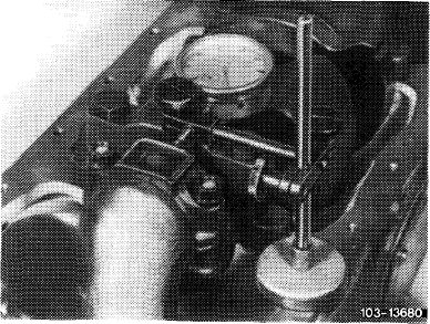
10 Provide screws on threads and on screw head contact surface with oil and tighten to
80 Nm.
Note: Since January 1976 there are no more washers on crankshaft bearing bolts.
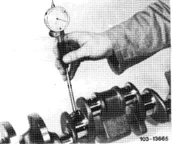
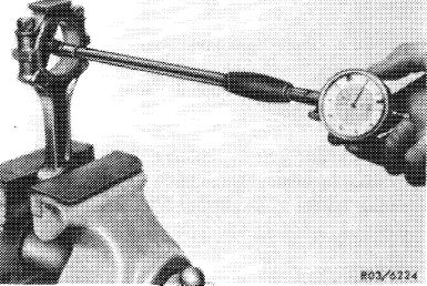
11 Measure end play of crankshaft bearings.
12 Rotate crankshaft manually and check whether shaft is freely running.
|
 |
||
|
|
|||
|
Associating connecting rod bearings and installing connecting rods
13 Check connecting rod bolts (03-310).
14 Recondition connecting rods and square (03-313).
|
 |
||
|
|
|||
|
R-3784
|
|||
|
|
|||
|
15 Mount connecting rod bearing caps while paying attention to identification. Tighten connecting rod nuts to 40-50 Nm.
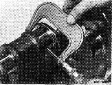
16 Measure basic bore in two directions. If a basic bore exceeds the specified value or is tapered, touch up bearing cap at its contact surface on a surface plate up to max 0.02 mm.
|
 |
||
|
|
|||
|
17 Insert connecting rod bearing shells, mount connecting rod bearing caps with bearing shells and tighten connecting rod nuts to 40—50 Nm.
Attention!
Connecting rod bearing shell in connecting rod has an oil bore for lubricating piston pin.
|
 |
||
|
|
|||
|
03.2-320/6 F 3
|
|||
|
|
|||
|
|
|||
|
18 Measure bearing dia and write down.
19 Measure crankpins, determine radial play (vertical runout) of connecting rod bearings.
Note: The bearing play can be corrected by exchanging bearing shells, while trying for mean value (0.04 mm) of specified bearing play. Crankshaft bearing shells without color code are thicker than those with a blue color code, but the fact must be taken into consideration that a wall thickness without and one with color code may overlap.
|
 |
||
|
|
|||
|
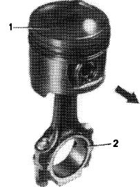
20 Mount piston on connecting rod (03—316).
21 Provide bearing shells, crankshaft, piston and cylinder with engine oil. Install connecting rod with piston (03-316).
Pay attention to identification.
|
 |
||
|
|
|||
|
103-S914!!
|
|||
|
|
|||
|
22 Tighten connecting rod nuts to 40—50 Nm initial torque and 90—100° angle of rotation.
|
 |
||
|
|
|||
|
23 Measure end play of. connecting rod bearing. Check connecting rod in piston for unobstructed operation.
Attention!
Disassemble and clean oil pump, renew if required. Renew oil pressure relief valve. Disassemble oil filter top and clean. Carefully clean air-oil cooler.
Install initial operation oil filter element. Change engine oil and oil filter element after 1000—1500 km.
|
 |
||
|
|
|||
|
03.2-320/7 F 3
|
|||
|
|
|||
|
|
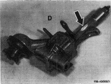
||||
|
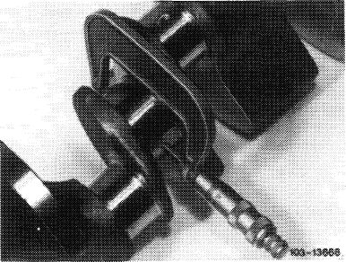
Crankshafts with riveted-on additional weight may not be used together with oil pumps, which are provided with a recess (arrow) on housing shaft.
|
 |
|||
|
|
||||
|
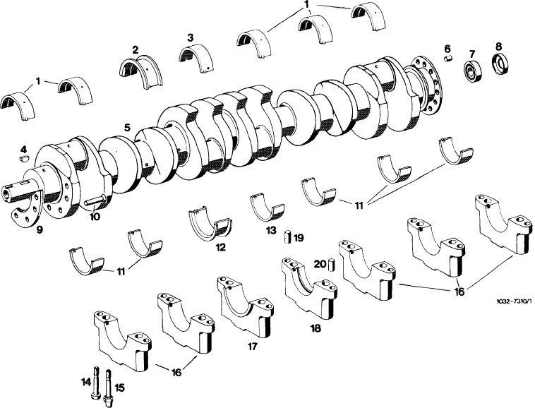
Crankshaft and bearing shells
|
||||
 |
||||
|
|
||||
|
1 Crankshaft bearing shells with oil groove and oil bore for bearing 1, 2, 5, 6 and 7
2 Fitted bearing shell with oil groove and oil bore for bearing 3
3 Crankshaft bearing shell with 2 oil pockets and 2 oil bores for bearing 4
4 Woodruff key
5 Crankshaft
6 Cyl. pin 10h8 x 18
7 Radial ball bearing
8 Closing ring
9 Additional weight
10 4 Countersunk rivets 6 x 28 mm DIN 661 MUSt 34
11 1 st version crankshaft bearing shells without oil groove and oil bore for bearing cap 1, 2, 5, 6 and 7 and crankshaft with T-bore
2nd version crankshaft bearing shells with oil groove and oil bore for bearing cap 1, 2, 5, 6 and 7 and crankshaft with 360° tapered bore
|
12
|
1st version fitted bearing shell without oil groove and oil bore for crankshaft with T-bore
2nd version fitted bearing shell with oil groove and
011 bore for crankshaft with 360° tapered bore Crankshaft bearing shell without oil groove and oil bore for bearing cap 4
12 screws for crankshaft bearing cap
2 screws for crankshaft bearing cap (for fastening
oil pump)
Crankshaft bearing cap 1, 2, 5, 6 and 7
Crankshaft bearing cap 4 (fitted bearing)
Crankshaft bearing cap 4 (with oil groove)
7 cyl. pins 10 m 6 x 16
7 cyl. pins 8 m 6 x 16
|
||
|
13
14 15
16 17 18 19 20
|
||||
|
|
||||
|
03.2-320/8 F 3
|
||||
|
|
||||