Replacing front crankshaft radial oil seal
|
|
|||||||||||||||||||||||||||||||||||
|
03—324 Replacing front crankshaft radial oil seal
|
|||||||||||||||||||||||||||||||||||
|
|
|||||||||||||||||||||||||||||||||||
|
Tightening torques
|
Nm
|
||||||||||||||||||||||||||||||||||
|
|
|||||||||||||||||||||||||||||||||||
|
|||||||||||||||||||||||||||||||||||
|
|
|||||||||||||||||||||||||||||||||||
|
Puller for balance disc
|
 |
116 589 10 33 00
|
|||||||||||||||||||||||||||||||||
|
|
|||||||||||||||||||||||||||||||||||
|
Holder
|
 |
116 589 01 40 00 or
|
|||||||||||||||||||||||||||||||||
|
|
|||||||||||||||||||||||||||||||||||
|
Holder
|
 |
110 589 00 40 00
|
|||||||||||||||||||||||||||||||||
|
|
|||||||||||||||||||||||||||||||||||
|
27 mm socket 1/2″ square
|
 |
001 589 65 09 00
|
|||||||||||||||||||||||||||||||||
|
|
|||||||||||||||||||||||||||||||||||
|
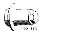
Puller for spacer
|
 |
616 589 00 33 00
|
|||||||||||||||||||||||||||||||||
|
|
|||||||||||||||||||||||||||||||||||
|
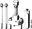
Radial oil seal installer
|
 |
110 589 07 61 00
|
|||||||||||||||||||||||||||||||||
|
|
|||||||||||||||||||||||||||||||||||
|
Note
|
 |
||||||||||||||||||||||||||||||||||
|
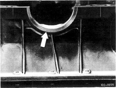
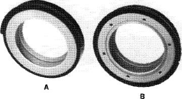
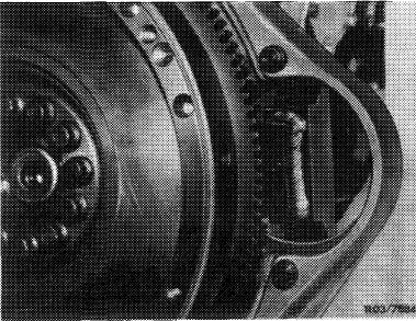
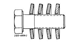
Install radial sealing rings, part no. 004 997 66 47 (twc component ring) or 003 997 03 47 (solid viton ring), with all-around shoulder only in engines with oil pan milled flat (arrow).
Radial sealing rings, part no. 008 997 04 47 (two-component ring) or 008 997 05 47 (solid viton ring) with half-round shoulder are provided for oil pans not milled flat.
Prior to installation, provide all radial sealing rings with longterm grease between sealing lip and dust lip.
|
|||||||||||||||||||||||||||||||||||
|
|
|||||||||||||||||||||||||||||||||||
|
03.2-324/1 F 3
|
|||||||||||||||||||||||||||||||||||
|
|
|||||||||||||||||||||||||||||||||||
|
|
|||
|
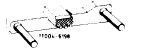
Install radial oil seals with a half shoulder in engines without a surface milled oil pan.
|
|||
|
|
|||
 |
|||
|
|
|||
|
A Radial oil seal with half shoulder B Radial oil seal with full shoulder
|
|||
|
|
|||
|
Removal
|
 |
||
|
1 Remove radiator and fan.
2 Remove pulley (1) and vibration damper (4) (03-340).
|
|||
|
|
|||
|
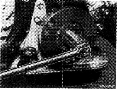
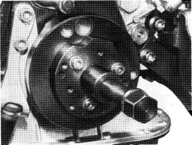
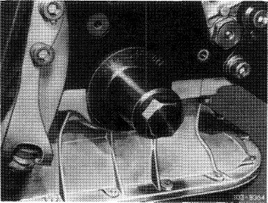
3 Loosen bolt on crankshaft.
|
 |
||
|
|
|||
|
03.2-324/2 F2
|
|||
|
|
|||
|
|
|||
|
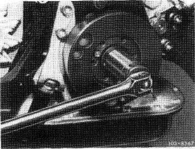
4 Counterhold crankshaft with holder.
|
 |
||
|
|
|||
|
Holder 100 589 00 40 00
|
|||
|
|
|||
|
Holder 116 589 01 40 00 when starter is removed
|
 |
||
|
|
|||
|
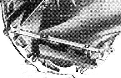
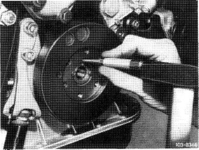
5 Mark balance disc and crankshaft together with a punch mark.
|
 |
||
|
|
|||
|
6 Pull off balance disc with an extractor.
|
303-8363
|
||
|
|
|||
|
03.2-324/3
|
|||
|
|
|||
|
|
|||
|
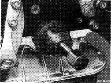
7 Press out radial oil seal with a screwdriver.
Attention!
Be careful not to damage crankshaft journals and
radial oil seal bore.
|
|||
|
|
|||
|
8 If wear can be felt, pull off spacer with an extractor.
|
 |
||
|
|
|||
|
Installation
|
|||
|
|
|||
|
9 Deburr and clean radial oil seal bore.
Note: If the removed radial sealing ring has been leaking at outer shoulder, coat new radial sealing ring prior to insertion on outer shoulder in range of joints with sealing compound, part no. 001 989 29 20 or part no. 001 989 46 20. Permit sealing compound to harden for approx. 3 hours and do not remove inserting tool until then.
|
|||
|
|
|||
|
10 Fill new radial sealing ring behind sealing lip with longterm grease.
11 Insert radial sealing ring with inserting tool. For radial sealing rings inserted with sealing compound, remove inserting tool only after 10—15 minutes.
Attention!
The radial oil seal must be at an exact right angle to the crankshaft journal, since otherwise a perfect seal cannot be reached.
|
 |
||
|
|
|||
|
03.2-324/4 F 3
|
|||
|
|
|||
|
|
|||
|
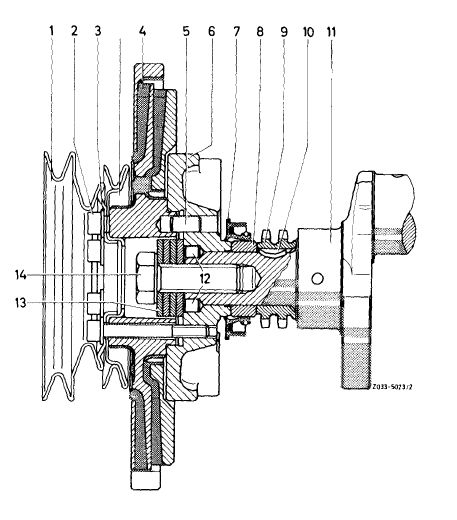
12 Install new spacing ring or turn spacing ring used up to now around and mount in such a manner that the worn groove comes to rest toward the rear.
|
|||
|
|
|||
|
13 Place balance disc on crankshaft, that the dowel pin bores align.
Note: The balance disc is located on the crankshaft by two offset dowel pins.
14 Pull balance disc on to crankshaft with
M 18×1.5×45 bolt and one belleville spring washer.
Knock in both dowel pins.
|
 |
||
|
|
|||
|
15 Install four belleville spring washers with concave surface facing bolt head.
16 Tighten bolt on crankshaft to torque of 400 Nm (40 kpm), while counterholding the crankshaft with a holder.
|
 |
||
|
|
|||
|
17 Install vibration damper, pulley, fan and radiator (03-340).
|
|||
|
|
|||
|
03.2-324/5 F 3
|
|||
|
|
|||