Checking and reconditioning crankshaft
|
|
||||||||||||||||||||||||||||||||||||||||||||||||||||||
|
03—318 Checking and reconditioning crankshaft
|
||||||||||||||||||||||||||||||||||||||||||||||||||||||
|
|
||||||||||||||||||||||||||||||||||||||||||||||||||||||
|
Data
|
||||||||||||||||||||||||||||||||||||||||||||||||||||||
|
|
||||||||||||||||||||||||||||||||||||||||||||||||||||||
|
||||||||||||||||||||||||||||||||||||||||||||||||||||||
|
|
||||||||||||||||||||||||||||||||||||||||||||||||||||||
|
Crankshaft journal dia. for mounting compensating weight
|
0.030
|
|||||||||||||||||||||||||||||||||||||||||||||||||||||
|
|
||||||||||||||||||||||||||||||||||||||||||||||||||||||
|
Permissible deviation of crankshaft journal prior to mounting compensating weight
|
from cyl. shape
|
0.005
|
||||||||||||||||||||||||||||||||||||||||||||||||||||
|
from true1)
|
0.030
|
|||||||||||||||||||||||||||||||||||||||||||||||||||||
|
|
||||||||||||||||||||||||||||||||||||||||||||||||||||||
|
Permissible deviation of crank pins and crankshaft bearing journals from true
|
0.0025
|
|||||||||||||||||||||||||||||||||||||||||||||||||||||
|
|
||||||||||||||||||||||||||||||||||||||||||||||||||||||
|
Permissible deviation of crank pin cyl. line from parallel
|
0.010
|
|||||||||||||||||||||||||||||||||||||||||||||||||||||
|
|
||||||||||||||||||||||||||||||||||||||||||||||||||||||
|
Permissible deviation of running surfaces of fitted bearing from parallel1)
|
0.020
|
|||||||||||||||||||||||||||||||||||||||||||||||||||||
|
|
||||||||||||||||||||||||||||||||||||||||||||||||||||||
|
Permissible deviation of running surface of rear radial sealing ring from concentric true1)
|
0.015
|
|||||||||||||||||||||||||||||||||||||||||||||||||||||
|
|
||||||||||||||||||||||||||||||||||||||||||||||||||||||
|
Permissible deviation of flywheel flange from axial true1)
|
0.010
|
|||||||||||||||||||||||||||||||||||||||||||||||||||||
|
|
||||||||||||||||||||||||||||||||||||||||||||||||||||||
|
Permissible deviation of crankshaft bearing journal from concentric true1)
|
journal II, VI
|
0.070
|
||||||||||||||||||||||||||||||||||||||||||||||||||||
|
0.100
|
||||||||||||||||||||||||||||||||||||||||||||||||||||||
|
journal III, IV, V
|
||||||||||||||||||||||||||||||||||||||||||||||||||||||
|
|
||||||||||||||||||||||||||||||||||||||||||||||||||||||
|
Fillets on crankshafts and crank pins
|
2.5 to 3
|
|||||||||||||||||||||||||||||||||||||||||||||||||||||
|
|
||||||||||||||||||||||||||||||||||||||||||||||||||||||
|
03.2-318/1 F3
|
||||||||||||||||||||||||||||||||||||||||||||||||||||||
|
|
||||||||||||||||||||||||||||||||||||||||||||||||||||||
|
|
||||
|
when new
|
74-84
|
|||
|
|
||||
|
Scleroscope hardness of crankshaft bearing journals and crank pins
|
boundary value
|
602>
|
||
|
|
||||
|
Permissible unbalance of crankshaft
|
15 cmg
|
|||
|
|
||||
|
1) When mounting crankshaft on outer crankshaft bearing journal I and VII after one full turn.
2) Boundary value should be available at min. 2/3 of journal circumference.
|
||||
|
|
||||
|
Special tool
|
||||
|
|
||||
|
Impact hardness tester
|
 |
000 589 20 21 00
|
||
|
|
||||
|
Self-made tool
|
||||
|
|
||||
|
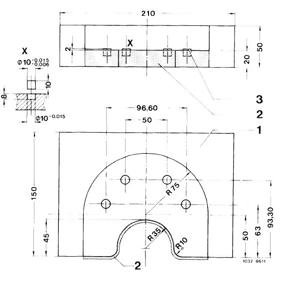
Rivet support for riveting counterweight to crankshaft.
|
 |
|||
|
|
||||
|
03.2-318/2 F3
|
||||
|
|
||||
|
|
|||
|
Note
|
 |
||
|
Since December 1978, the crankshaft of engine 110
is provided with an additional weight.
Remove additional weight when machining first crank
pin.
After machining crank pin, rivet additional weight on
again. Then check crankshaft for runout, and balance
together with flywheel and balancing disc, also when
re-using the old additional weight.
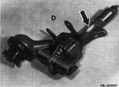
The crankshaft with riveted-on additional weight may be used only together with a modified oil pump which is provided with a recess (arrow) on housing shaft.
When checking and reconditioning crankshafts, proceed in sequence of the following diagram and pertinent explanations.
For grinding crank pins, a difference of only one repair stage per crankshaft is permitted.
|
|||
 |
|||
|
|
|||
|
03.2-318/3 F3
|
|||
|
|
|||
|
|
||
 |
||
|
|
||
|
03.2-318/4 F3
|
||
|
|
||
|
|
|||
|
Explanations concerning diagram
|
|||
|
|
|||
|
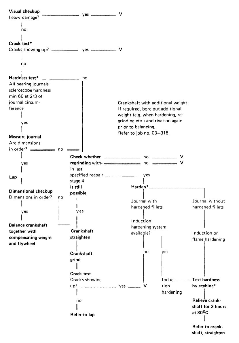
Crack test
|
|||
|
|
|||
|
Clean crankshaft. Bearing journals should be free of oil and grease. Magnetize crankshaft and apply fluorescent powder (flux). A color penetration method (insertion in bath or with spray can) can also be applied.
Aids: paint or fluorescent powder, cleaning agent, developer.
|
|||
|
|
|||
|
Hardness test
|
 |
||
|
Test hardness with impact hardness tester (scleros-cope hardness).
Scleroscope hardness of 60 should be available at 2/3 of journal circumference.
|
|||
|
|
|||
|
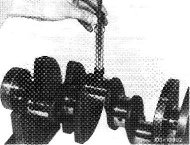
Hardening
|
 |
||
|
Journals without hardened fillets can be hardened inductively or by flame hardening. Journals with hardened fillets (arrows) should be inductance-hardened on principle. If this is not possible, scrap crankshaft.
|
|||
|
|
|||
|
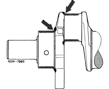
When hardening journals without hardened fillets, maintain distance A between runout of hardened surface and fillet (4—5 mm).
|
|||
|
|
|||
 |
|||
|
|
|||
|
03.2-318/5 F2
|
|||
|
|
|||
|
|
||
|
Checking hardening procedure
|
||
|
|
||
|
For a good hardening job, test adjustment of hardening plant by metallographic grinding tests.
These tests can be made by testing scrapped crankshafts.
|
||
|
|
||
|
Check hardening by etching surface of journal with a 2% alcoholic nitric acid (HNO3).
No dark spots should show up at surface of journal. Non-hardened fillets will become dark.
|
||
|
|
||
|
The hardened fillets, on the other hand, should be as bright as surface of journal.
For comparison, perform an etching job on a metallo-graphically controlled journal.
Then, carefully wash off nitric acid by means of alcohol.
|
||
|
|
||
|
Corrosion protection
|
||
|
|
||
|
Crankshafts which are not immediately installed again should be lubricated with engine initial operation oil (SAE 30).
|
||
|
|
||
|
03.2-318/6 F2
|
||
|
|
||
|
|
|||
|
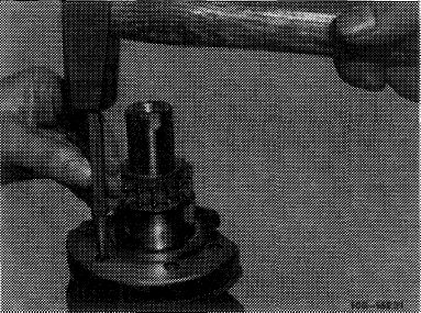
Riveting additional weight off and on
1 Punch mark countersunk rivet 6 x 28 mm accurately in center.
|
 |
||
|
|
|||
|
2 Drill into rivet heads with a 6.5 mm dia. drill and knock out.
|
 |
||
|
|
|||
|
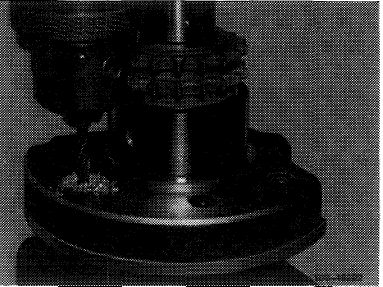
3 Slip-on new or former, undamaged additional weight together with 4 countersunk rivets.
|
 |
||
|
|
|||
|
4 Introduce crankshaft.into a suitable steel tube (approx. 165 mm dia. x 420 mm long) and place self-made rivet support (2) underneath.
|
 |
||
|
1 Steel tube 165 mm dia. x 420 mm long
2 Self-made rivet support
3 Snap die
|
|||
|
|
|||
|
03.2-318/7 F3
|
|||
|
|
|||
|
|
|||||
|
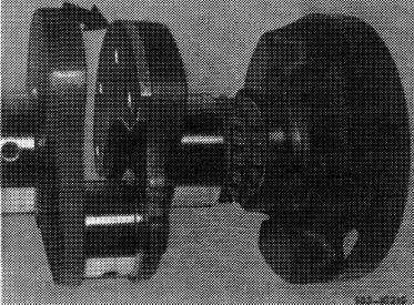
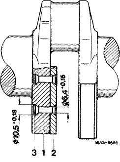
5 Rivet countersunk rivet by means of a hydraulic press. The additional weight should then rest fully against crankshaft cheek without leaving any intermediate space.
6 Then check crankshaft for runout of bearing journals and balance together with balancing disc and flywheel, even if the former additional weight is used again.
|
 |
||||
|
1 Crankshaft
2 Additional weight 1 TO 031 05 01
3 Countersunk rivet 6 x 28 mm DIN 661 MUSt 34
|
|||||
|
|
|||||
|
Series production of riv®tsd-on additions! weight starting December 1978
|
|||||
|
|
|||||
|
starting engine end no.
|
starting chassis end no.
|
||||
|
|
|||||
|
110 992 -10-038
-12-062 390
|
116.020-112 253
|
||||
|
|
|||||
|
923
|
–10–012665 -12-015613
|
123.030-025 675 123.050-002 801
|
|||
|
|
|||||
|
932
|
–10–009748 -12-002 556
|
116.020-112 253
|
|||
|
|
|||||
|
110 984 „10-014 634 -12-051 160
|
123.033-050 600 123.053-013 292
|
||||
|
|
|||||
|
110.984 „10-014 634 -12-051 160
|
123.093-001 229
|
||||
|
|
|||||
|
110.985 -10-011 106 -12-052 660
|
116.024/025-131 270
|
||||
|
|
|||||
|
110.986 -10-002 276 -12-005 142
|
107.022-006 288 107.042-005 285
|
||||
|
|
|||||
|
03.2-318/8 F3
|
|||||
|
|
|||||