Removal and installation of coolant pump
|
|
|||||
|
20—210 Removal and installation of coolant pump
|
|||||
|
|
|||||
|
Tightening torques
|
Model
|
Nm
|
|||
|
|
|||||
|
116
|
6-10
|
||||
|
|
|||||
|
Drain plug of radiator
|
|||||
|
|
|||||
|
123, 126
|
1.5-21)
|
||||
|
|
|||||
|
Viscofan coupling to coolant pump
|
20-25
|
||||
|
|
|||||
|
Coolant pump to coolant pump housing
|
10
|
||||
|
|
|||||
|
’) This torque can be obtained by means of a washer or a coin.
|
|||||
|
|
|||||
|
Special tools
|
|||||
|
|
|||||
|
Tester for cooling system
|
 |
001 589 48 21 00
|
|||
|
11004- S32S
|
|||||
|
|
|||||
|
Radiator cap with hose for leak test
|
 |
605 589 00 25 00
|
|||
|
|
|||||
|
7 mm socket on flexible shaft for hose clamps
|
123 589 12 09 00
|
||||
|
|
|||||
|
Note
|
 |
||||
|
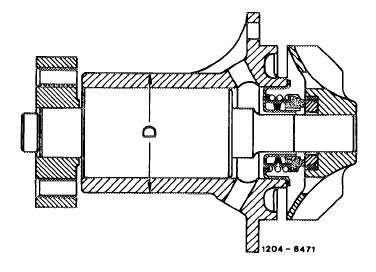
Since October 1979 coolant pump part No. 110 200 01 20 is replaced by coolant pump part No. 115 200 00 20 as standard equipment, identified by smaller OD (D) of bearing housing of 48 mm (formerly 52 mm).
Reason: standardized with engines 615 and 616.
|
|||||
|
|
|||||
|
20.8-210/1 F2
|
|||||
|
|
|||||
|
|
|||||
|
Start of series
|
|||||
|
|
|||||
|
Model Engine
|
Engine end Chassis end
|
||||
|
No.
|
No.
|
||||
|
|
|||||
|
116.120 617.950 015494
|
015164
|
||||
|
|
|||||
|
Attention!
Coolant pump 110 200 01 20 together with seal within scope of 110 200 09 20 are again available as a spare part.
|
|||||
|
|
|||||
|
Removal
|
 |
||||
|
1 Completely drain coolant (20-010).
2 Remove fan with viscofan coupling.
3 Remove alternator V-belt and coolant pump pulley.
|
|||||
|
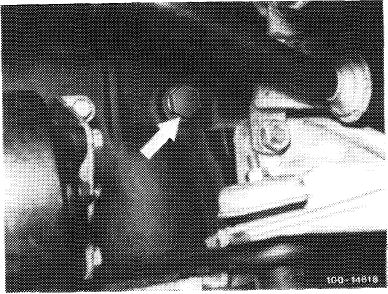
Drain plug on cylinder crankcase (arrow)
|
|||||
|
|
|||||
|
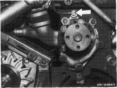
4 Unscrew coolant pump and remove.
|
 |
||||
|
|
|||||
|
Installation
|
|||||
|
|
|||||
|
5 Position coolant pump with new gasket and tighten fastening screws to 10 Nm.
6 For further installation proceed vice versa to removal.
7 Tension alternator V-belt (13-340).
8 Pressure-test cooling system with tester (approx. 1 bar gage pressure).
|
|||||
|
|
|||||
|
20.8-210/2 F2
|
|||||
|
|
|||||