Removal and installation of chain tensioner
|
|
||||||||||||||||||||||||||||||
|
05—310 Removal and installation of chain tensioner
|
||||||||||||||||||||||||||||||
|
|
||||||||||||||||||||||||||||||
|
Tightening torques
|
Nm
|
|||||||||||||||||||||||||||||
|
|
||||||||||||||||||||||||||||||
|
Ball locating ring (oil jet) in chain
|
25
|
|||||||||||||||||||||||||||||
|
|
||||||||||||||||||||||||||||||
|
Plug
|
50
|
|||||||||||||||||||||||||||||
|
|
||||||||||||||||||||||||||||||
|
Threaded ring
|
50
|
|||||||||||||||||||||||||||||
|
|
||||||||||||||||||||||||||||||
|
Special tool
|
||||||||||||||||||||||||||||||
|
|
||||||||||||||||||||||||||||||
|
Wrench socket 10 mm, 1/2″ square, 140 mm long
|
 |
000 589 05 07 00
|
||||||||||||||||||||||||||||
|
Holder for chain tensioner
|
110 589 02 31 00
|
|||||||||||||||||||||||||||||
|
||||||||||||||||||||||||||||||
|
|
||||||||||||||||||||||||||||||
|
Note
|
 |
|||||||||||||||||||||||||||||
|
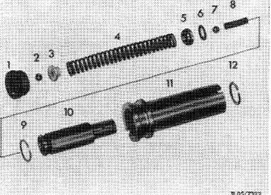
Chain tensioners are available in two versions and interchangeable with each other.
|
||||||||||||||||||||||||||||||
|
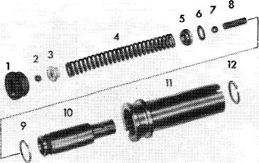
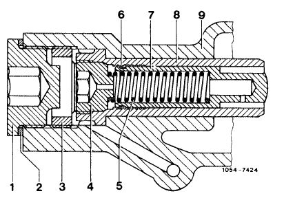
1st version
1 Ball seat ring with 3.0 mm bore
2 Ball
3 Ball cage
4 Spring
5 Valve disc
6 O-ring
|
7 Ball
8 Spring
9 Snap ring
10 Pressure pin
11 Housing
12 Snap ring
|
|||||||||||||||||||||||||||||
|
R 05/7329
|
||||||||||||||||||||||||||||||
|
|
||||||||||||||||||||||||||||||
|
05.2-310/1 F3
|
||||||||||||||||||||||||||||||
|
|
||||||||||||||||||||||||||||||
|
|
||||
|
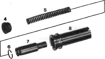
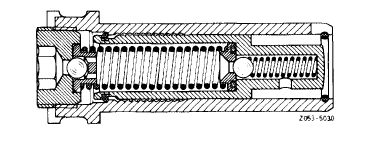
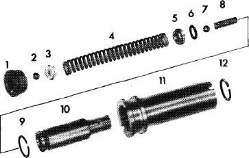
The 2nd version chain tensioner does not have valves and its oil jet (4) has a 1.1 mm bore.
Difference when installed:
1st version: bore in ball locating ring closed by ball.
2nd version: bore in oil jet can be checked for plugging with a piece of 1 mm dia. wire.
2nd version
4 Oil nozzle 7 Pressure pin with 1.1 mm bore 8 Housing
5 Spring
6 Snap ring
|
 |
|||
|
RO5-7322/2
|
||||
|
|
||||
|
Attention!
Without counterpressure from the clamping rail the pressure pin (10) with snap ring (9) will be pressed forward up to the stop by spring (4).
|
 |
|||
|
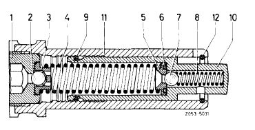
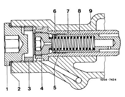
Chain tensioner in operating position
1 Ball locating ring 7 Ball
|
||||
|
2 Ball
3 Ball cage
4 Spring
5 Valve disc
6 O-ring
|
8 Spring
9 Snap ring
10 Pressure pin
11 Housing
12 Snap ring
|
|||
|
|
||||
|
|
||||
|
The pressure pin cannot be pressed back beyond the saw tooth type catch in assembly position ,,A”.
Thus the chain tensioner must be disassembled before each installation to move the pressure pin to assembly position ,,A”, since otherwise the timing chain would be too tight.
|
 |
|||
|
|
||||
|
Chain tensioner in assembly position.
|
 |
|||
|
|
||||
|
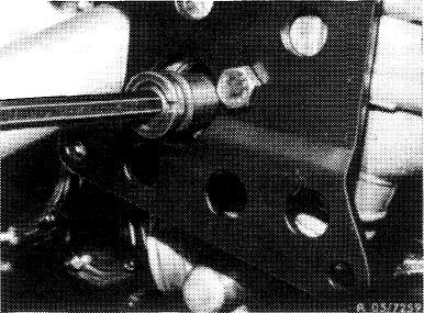
Removal
|
 |
|||
|
1 Remove battery and compressor of models with an air conditioner.
|
||||
|
|
||||
|
05.2-310/2 F2
|
||||
|
|
||||
|
|
|||
|
2 Remove plug with the 17 mm screwdriver socket.
|
 |
||
|
|
|||
|
Attention!
If a 2nd version chain tensioner is installed, during assembly it will be sufficient to first remove spring (5) of an installed chain tensioner at the chain drive (e.g. remove camshaft sprocket or tensioning rail).
|
 |
||
|
|
|||
|
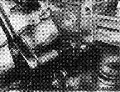
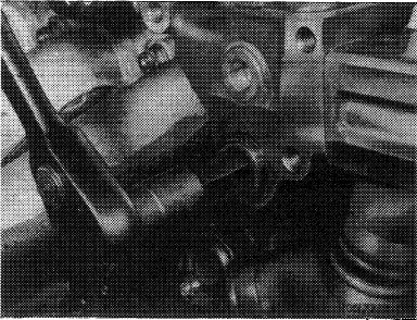
3 Loosen ball locating ring (oil jet) by about 2 turns with a socket wrench.
This requires that the threaded ring be tightened.
|
 |
||
|
|
|||
|
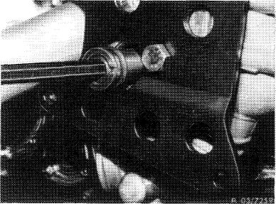
4 Remove threaded ring with a 19 mm screwdriver socket.
|
 |
||
|
|
|||
|
05.2-310/3 F2
|
|||
|
|
|||
|
|
|||
|
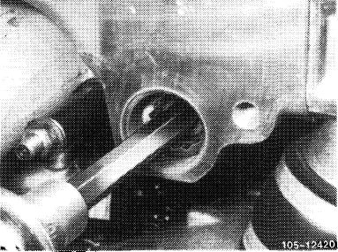
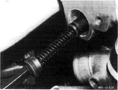
5 Pull out chain tensioner with a 10 mm socket wrench.
This requires that the socket wrench be canted slightly and the chain tensioner turned to the right.
For pulling out stuck chain tensioner, screw a M 18 x 1.5 screw into chain tensioner housing instead of ball seat ring (oil nozzle).
|
 |
||
|
|
|||
|
Disassembling
|
 |
||
|
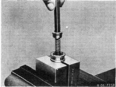
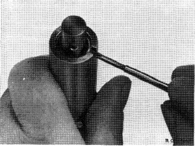
6 Clamp chain tensioner in holders.
7 Unscrew ball seat ring (oil nozzle) with hex. socket wrench.
When disassembling be careful of the spring force and apply counterpressure with a socket wrench.
|
|||
|
|
|||
|
8 Remove spring (4) with ball cage (3), ball (2) and valve disc (5).
9 Relief chain tensioner, remove ball (7) and spring (8) from pressure limit valve.
|
 |
||
|
|
|||
|
10 Take off snap ring (12) with a small screwdriver.
11 Pull out pressure pin toward front (pressure direction).
12 Clean out parts thoroughly.
|
 |
||
|
|
|||
|
05.2-310/4 F3
|
|||
|
|
|||
|
|
|||
|
Assembling and installation
|
 |
||
|
1st version
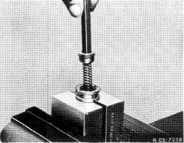
13 Clamp housing (11) with installed snap ring (12) in holders.
14 Install pressure pin (10) with snap ring (9) from above. The snap ring rests on the assembly chamfer and prevents the pressure pin from falling through onto a catch.
|
|||
|
|
|||
|
R 05/7322
|
|||
|
|
|||
|
15 Install spring (8) and ball (7) of pressure limit valve.
16 Install spring (4) with valve disc (5) and O-Ring (6).
17 Place ball cage (3) and ball (2) on spring (4).
|
|||
|
|
|||
|
18 Install ball locating ring (1) on ball cage with an internal socket wrench. Compress spring (4) and screw ball locating ring into housing by about 2 turns.
Attention!
Don’t tighten ball locating ring, since otherwise the pressure pin will jump forward and the chain tensioner will have to be disassembled again.
|
 |
||
|
|
|||
|
19 Guide chain tensioner into chain tensioner hole in cylinder head with an internal socket wrench.
Attention!
Don’t apply knocks to socket wrench, since otherwise the pressure pin will jump forward.
|
 |
||
|
|
|||
|
05.2-310/5 F2
|
|||
|
|
|||
|
|
|||
|
20 Install threaded ring (15) and tighten to a torque of 50 Nm.
21 Tighten ball locating ring to 25 Nm whereby the pressure pin must make a clicking noise as it jumps forward.
22 Install plug (13) with seal (14) and torque to 50 Nm.
|
 |
||
|
|
|||
|
2nd version
|
 |
||
|
23 Guide housing (8) into cylinder head.
|
|||
|
|
|||
|
24 Install threaded ring (3) and torque to 50 Nm.
|
 |
||
|
|
|||
|
25 Install pressure pin (7) with installed snap ring (6) and spring (5) in housing and torque oil jet (4) to 25 Nm, whereby the pressure pin must make a clicking noise as it jumps forward.
26 Install plug (1) with seal (2) and torque to 50 Nm.
|
 |
||
|
|
|||
|
05.2-310/6 F3
|
|||
|
|
|||