Removal and installation of engine (oil filling capacity)
|
01-030 Removal and installation of engine (oil filling capacity)
|
||||||||||||||||||||||||||||||
|
|
||||||||||||||||||||||||||||||
|
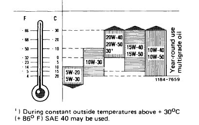
Specified viscosity classes
according to SAE
during constant outside temperatures
|
 |
|||||||||||||||||||||||||||||
|
|
||||||||||||||||||||||||||||||
|
Oil filling capacity in liters (for approved engine oil grades refer to specifications for service products)
|
||||||||||||||||||||||||||||||
|
|
||||||||||||||||||||||||||||||
|
Color code of oil dipstick
|
total capacity when refilling engine
|
|||||||||||||||||||||||||||||
|
|
||||||||||||||||||||||||||||||
|
||||||||||||||||||||||||||||||
|
|
||||||||||||||||||||||||||||||
|
Fastening screw for oil filter lower half
|
M 12
|
40
70
|
||||||||||||||||||||||||||||
|
|
||||||||||||||||||||||||||||||
|
Screws for engine carrier on engine mount front
|
||||||||||||||||||||||||||||||
|
|
||||||||||||||||||||||||||||||
|
M 10
|
40
|
|||||||||||||||||||||||||||||
|
|
||||||||||||||||||||||||||||||
|
Special tools
|
||||||||||||||||||||||||||||||
|
|
||||||||||||||||||||||||||||||
|
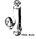
Tester for cooling system and radiator cap
|
 |
001 589 48 21 00
|
||||||||||||||||||||||||||||
|
|
||||||||||||||||||||||||||||||
|
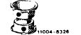
Double connection for radiator cap test in combination with tester
|
 |
000 589 73 63 00
|
||||||||||||||||||||||||||||
|
|
||||||||||||||||||||||||||||||
|
Radiator cap with hose for leak test
|
 |
605 589 00 25 00
|
||||||||||||||||||||||||||||
|
|
||||||||||||||||||||||||||||||
|
Conventional tool
|
||||||||||||||||||||||||||||||
|
|
||||||||||||||||||||||||||||||
|
Engine hoist (Motordirigent) size 1.5
|
e.g. made by Backer, D-5630 Remscheid order no. 3178
|
|||||||||||||||||||||||||||||
|
|
||||||||||||||||||||||||||||||
|
01.2-030/1 F3
|
||||||||||||||||||||||||||||||
|
Remove and install engine with transmission by means of an engine hoist in diagonal position.
If removal and installation is performed on a lifting platform, the engine of model 126 can be placed on cross yoke center piece at the rear during installation.
|
 |
||
|
|
|||
|
Removal
|
 |
||
|
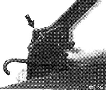
1 On model 123 and 126 move engine hood into 90° position and let left-hand locking lever (arrow) engage.
On other models, remove engine hood.
2 Disconnect battery cable.
|
|||
|
|
|||
|
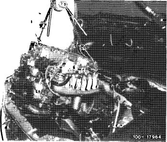
3 Drain coolant (arrow).
4 Disconnect and close lines for air oil cooler and transmission oil cooler on radiator and close, so that no oil will run out.
|
 |
||
|
|
|||
|
5 Remove radiator together with air oil cooler, while suspending fan cover over fan.
|
|||
|
|
|||
|
01.2-030/2 F3
|
|||
|
|
|||
|
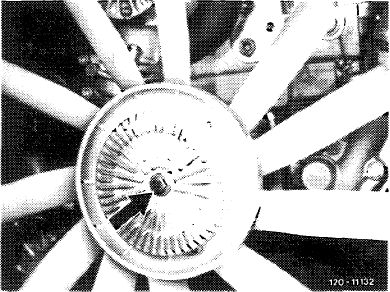
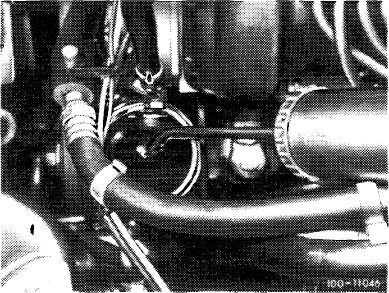
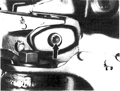
6 Remove fan.
For this purpose, loosen screw (arrow) on magnetic fan.
|
|
 |
|
|
|
|||
|
7 On vehicles with air conditioning, unscrew refrigerant compressor and put aside with lines connected. When removing refrigerant compressor, drain air conditioning system (83—516).
|
 |
||
|
|
|||
|
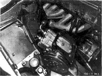
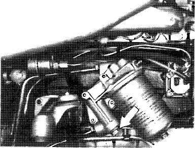
8 Disconnect lines at oil pressure pump. Only loosen bolts (arrows) to detach oil pressure pump.
|
 |
||
|
|
|||
|
9 Draw oil out of power steering pump tank.
10 Disconnect hoses at power steering pump.
|
 |
||
|
|
|||
|
01.2-030/3 F 3
|
|||
|
11 Disconnect electric harness for starter motor and alternator.
12 Disconnect all electric connections on engine.
|
|||
|
|
|||
|
13 Remove longitudinal control shaft.
|
 |
||
|
|
|||
|
14 Disconnect all coolant, vacuum, oil and electric lines leading to the engine.
|
 |
||
|
|
|||
|
15 Pull off TDC transmitter wires at test socket. This requires unscrewing test socket at holder.
16 Detach exhaust pipes at exhaust manifold and exhaust strut at transmission.
|
 |
||
|
|
|||
|
01.2-030/4 F3
|
|||
|
|
17 Unscrew engine shock absorbers left and right (00-240). |
 |
|
|
|
|||
|
|
|||
|
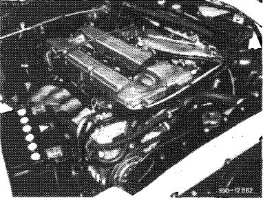
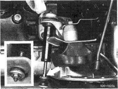
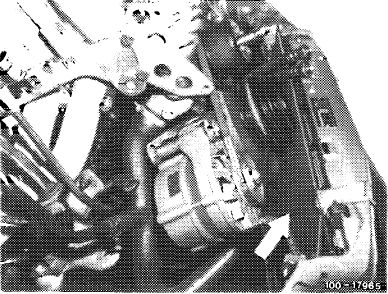
18 Remove engine mounting bolts from engine mount. Model 114 from above.
Models 107, 116, 123 and 126 from bottom of vehicle (arrow).
|
100-11491
|
||
|
|
|||
|
19 Remove rear engine carrier with engine mount.
|
|||
|
|
|||
|
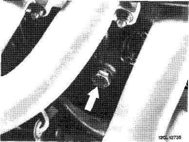
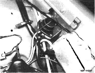
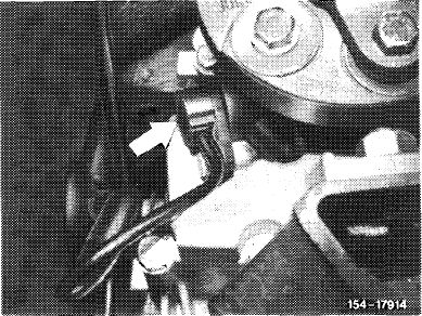
20 Disconnect tachometer shaft on transmission.
Models with inductance transmitter (arrow): Disconnect inductance transmitter for tachometer. For this purpose, unscrew screw M 6 and pull out inductance transmitter.
|
 |
||
|
|
|||
|
01.2-030/5 F3
|
|||
|
21 Disconnect propeller shaft on transmission and slide back.
Support propeller shaft, so that shaft will not abut against transmission flange when installing engine.
22 Loosen all connections and shift rods on transmission.
|
||||
|
|
||||
|
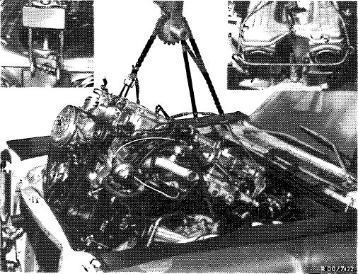
23 Attach engine at rear and front to suspension eyes.
24 Lift engine with transmission by means of engine hoist in an approx. 45° diagonal position. Make sure that the partition for unit compartment (model 126)
is not damaged, since its damping effects will be lost by absorbed splash water.
|
 |
|||
|
|
||||
|
Attention!
On vehicles with air conditioning, cover condenser with a hard fiber board (arrow).
|
 |
|||
|
|
||||
|
Installation
|
118-11166/1
|
|||
|
Attention!
When installing an engine because of previous bearing damage, flush out the oil cooler and oil hoses. Clean oil filter housing.
25 Check engine mounts, engine shock absorbers, coolant, oil and fuel hoses and replace them if necessary.
26 Prior to flanging-on manual transmission, check radial ball bearing in crankshaft and throw-out of clutch and renew, if required.
|
||||
|
|
||||
|
01.2-030/6 F3
|
||||
|
|
||||
|
27 Install engine and connect.
28 Adjust rear engine mount free of tension (00—220).
29 Connect propeller shaft.
30 Check all drain plugs for tight seat.
31 Add oil and coolant (20-010).
32 Check cooling system for leaks with leak tester.
Note: On vehicles with auxiliary heater, bleed coolant circuit (refer to repair instructions auxiliary heater 83-415).
33 Check coolant for antifreeze.
34 Clean air filter and renew, if required.
35 Check dwell angle and firing point.
36 Adjust idle speed and emission value (07.2-100).
37 Check regulating shaft for function.
|
||
|
|
||
|
01.2-030/7 F3
|