Removal and installation of piston
|
|
|||||||||||||||||||||||||||||||||||||||||||||||||||||||||||||||||||||||||||||||||||||||
|
03—316 Removal and installation of piston
|
|||||||||||||||||||||||||||||||||||||||||||||||||||||||||||||||||||||||||||||||||||||||
|
|
|||||||||||||||||||||||||||||||||||||||||||||||||||||||||||||||||||||||||||||||||||||||
|
Association piston — cylinder1 )
|
|||||||||||||||||||||||||||||||||||||||||||||||||||||||||||||||||||||||||||||||||||||||
|
|
|||||||||||||||||||||||||||||||||||||||||||||||||||||||||||||||||||||||||||||||||||||||
|
|||||||||||||||||||||||||||||||||||||||||||||||||||||||||||||||||||||||||||||||||||||||
|
|
|||||||||||||||||||||||||||||||||||||||||||||||||||||||||||||||||||||||||||||||||||||||
|
The smallest measured cylinder dia and the largest measured piston dia are decisive for association.
|
|||||||||||||||||||||||||||||||||||||||||||||||||||||||||||||||||||||||||||||||||||||||
|
|
|||||||||||||||||||||||||||||||||||||||||||||||||||||||||||||||||||||||||||||||||||||||
|
Piston code number and piston distance
|
|||||||||||||||||||||||||||||||||||||||||||||||||||||||||||||||||||||||||||||||||||||||
|
|
|||||||||||||||||||||||||||||||||||||||||||||||||||||||||||||||||||||||||||||||||||||||
|
Engine
|
|
||||||||||||||||||||||||||||||||||||||||||||||||||||||||||||||||||||||||||||||||||||||
|
|
|||||||||||||||||||||||||||||||||||||||||||||||||||||||||||||||||||||||||||||||||||||||
|
Normal compression
|
|||||||||||||||||||||||||||||||||||||||||||||||||||||||||||||||||||||||||||||||||||||||
|
|
|||||||||||||||||||||||||||||||||||||||||||||||||||||||||||||||||||||||||||||||||||||||
|
110.921 110.922 110.923 110.924 110.981 110.982
|
110.983 110.984 110.985 110.986 110.987
|
Std
|
37, 40, 50, 60, 64, 69 80M.83, 86′),89
|
Standback 0.20 to 0.70
|
|||||||||||||||||||||||||||||||||||||||||||||||||||||||||||||||||||||||||||||||||||
|
9.0±0.2 8.7 ±0.2
|
+ 0.5
|
38, 41, 51, 67, 70, 84,90
39, 42, 52, 68, 71, 85, 91
|
Standback 1.0 to 1.50
|
||||||||||||||||||||||||||||||||||||||||||||||||||||||||||||||||||||||||||||||||||||
|
+ 1.0
|
|||||||||||||||||||||||||||||||||||||||||||||||||||||||||||||||||||||||||||||||||||||||
|
|
|||||||||||||||||||||||||||||||||||||||||||||||||||||||||||||||||||||||||||||||||||||||
|
Low compression
|
|||||||||||||||||||||||||||||||||||||||||||||||||||||||||||||||||||||||||||||||||||||||
|
|
|||||||||||||||||||||||||||||||||||||||||||||||||||||||||||||||||||||||||||||||||||||||
|
8.0-0.4
|
|
0.25 standout up to 0.15 standback
|
||||||||||||||||||||||||||||||||||||||||||||||||||||||||||||||||||||||||||||||||||||
|
Standback 0.55 to 0.95
|
|||||||||||||||||||||||||||||||||||||||||||||||||||||||||||||||||||||||||||||||||||||||
|
|
|||||||||||||||||||||||||||||||||||||||||||||||||||||||||||||||||||||||||||||||||||||||
|
1 ) Installed in engine 110.984, 110.985, 110.986 and 110.987 as standard equipment. Not available as repair stages. Use only together with piston of same piston code number.
|
|||||||||||||||||||||||||||||||||||||||||||||||||||||||||||||||||||||||||||||||||||||||
|
|
|||||||||||||||||||||||||||||||||||||||||||||||||||||||||||||||||||||||||||||||||||||||
|
03.2-316/1 F3
|
|||||||||||||||||||||||||||||||||||||||||||||||||||||||||||||||||||||||||||||||||||||||
|
|
|||||||||||||||||||||||||||||||||||||||||||||||||||||||||||||||||||||||||||||||||||||||
|
|
|||||||||||||||||||||||||||||||||
|
Test values
|
New Wear limit
(Installation tolerance)
|
||||||||||||||||||||||||||||||||
|
|
|||||||||||||||||||||||||||||||||
|
|||||||||||||||||||||||||||||||||
|
|
|||||||||||||||||||||||||||||||||
|
Piston pin clearance
|
in conrod bushing
|
0.007 to 0.017
|
|||||||||||||||||||||||||||||||
|
|
|||||||||||||||||||||||||||||||||
|
in piston
|
0.002 to 0.011
|
||||||||||||||||||||||||||||||||
|
|
|||||||||||||||||||||||||||||||||
|
Piston ring gap
|
groove 1 groove 2 groove 3
|
0.30 to 0.45 0.30 to 0.45 0.25 to 0.40
|
1.0 0.8 0.8
|
||||||||||||||||||||||||||||||
|
|
|||||||||||||||||||||||||||||||||
|
Piston ring clearance
|
groove 1 groove 2 groove 3
|
0.05 to 0.08 0.03 to 0.06 0.01 to 0.04
|
0.15 0.08 0.08
|
||||||||||||||||||||||||||||||
|
|
|||||||||||||||||||||||||||||||||
|
Tightening torque
|
|||||||||||||||||||||||||||||||||
|
|
|||||||||||||||||||||||||||||||||
|
Connecting rod nuts
|
torque pressure
|
40-50 Nm
|
|||||||||||||||||||||||||||||||
|
|
|||||||||||||||||||||||||||||||||
|
torque angle
|
90-100°
|
||||||||||||||||||||||||||||||||
|
|
|||||||||||||||||||||||||||||||||
|
Special tools
|
|||||||||||||||||||||||||||||||||
|
|
|||||||||||||||||||||||||||||||||
|
Piston ring pliers
|
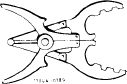 |
000 589 51 37 00
|
|||||||||||||||||||||||||||||||
|
|
|||||||||||||||||||||||||||||||||
|
Piston ring compressor
|
 |
000 589 04 14 00
|
|||||||||||||||||||||||||||||||
|
|
|||||||||||||||||||||||||||||||||
|
Note
|
 |
||||||||||||||||||||||||||||||||
|
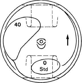
The piston version (std, + 0.5 or + 1.0), the group number (0, 1 or 2), the piston code (e.g. 40) and an arrow for forward direction are stamped in the piston crown.
|
|||||||||||||||||||||||||||||||||
|
|
|||||||||||||||||||||||||||||||||
|
The
|
group number is also stamped in the crankcase
|
||||||||||||||||||||||||||||||||
|
mating surface.
|
|||||||||||||||||||||||||||||||||
|
|
|||||||||||||||||||||||||||||||||
|
1034 – 5411
|
|||||||||||||||||||||||||||||||||
|
|
|||||||||||||||||||||||||||||||||
|
03.2-316/2 F3
|
|||||||||||||||||||||||||||||||||
|
|
|||||||||||||||||||||||||||||||||
|
|
|||
|
The group number of pistons (e.g. 1) is the same as the group number of cylinder bores (production).
This will guarantee the specified piston clearance.
When repairing, the cylinder bores should be honed according to the sizes of the existing pistons plus the piston clearance.
Pistons and piston pins are matched.
|
|||
|
|
|||
|
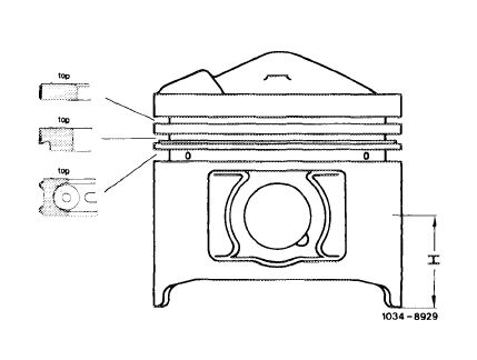
The measuring point for nominal diameter of pistons is offset by 90° in relation to piston pin axis at level H.
On used pistons the measured value does not necessarily correspond with nominal diameter of a new piston, since piston in range of measuring point and at shaft tab may „recede” already after a short operating period, that is, the nominal diameter may become smaller by up to 0.070 mm.
|
 |
||
|
Piston normal compression dimension H = 32 mm
|
|||
|
|
|||
|
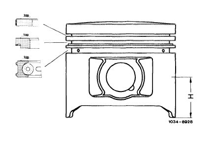
If used pistons are used again, make sure that the oil drain bores in 3rd piston ring groove are cleaned.
|
 |
||
|
Piston low compression and USA version dimension H = 32 mm
|
|||
|
|
|||
|
Removal
|
|||
|
|
|||
|
1 Take out connecting rod with piston from above.
|
|||
|
|
|||
|
2 Remove piston pin circlips and press out piston pin.
|
|||
|
|
|||
|
3 Repair and square connecting rod (03—313).
|
|||
|
|
|||
|
03.2-316/3 F3
|
|||
|
|
|||
|
|
||||
|
Installation
|
 |
103-8914/1
|
||
|
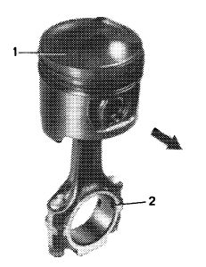
4 Place piston on connecting rod that arrow (1) faces in forward direction and circlip grooves (2) in connecting rod face to left side of engine (intake manifold).
Attention!
Don’t heat piston.
|
||||
|
|
||||
|
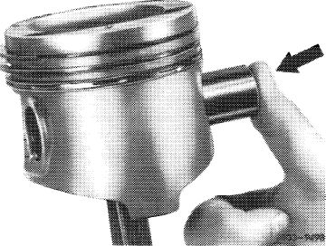
5 Press in piston pin coated with engine oil by hand.
|
||||
|
|
||||
 |
||||
|
|
||||
|
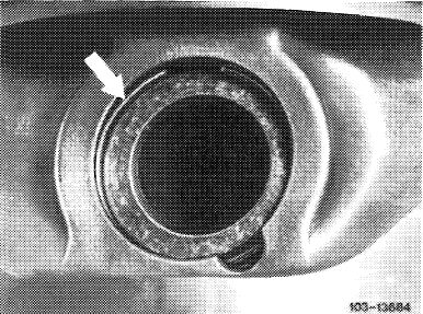
6 Insert piston pin circlips in grooves.
When installing used pistons, check piston ring gaps and clearances.
Check piston rings for easy movement.
7 Lubricate cleaned cylinder bores, conrod bearing journals, conrod bearing shells and the pistons.
|
 |
|||
|
|
||||
|
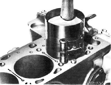
8 Distribute gaps of piston rings around piston circumference evenly.
9 Install piston ring compressor and guide in piston with arrow facing forward.
|
 |
|||
|
|
||||
|
03.2-316/4 F2
|
||||
|
|
||||
|
|
|||
|
10 Place connecting rod bearing caps with code numbers facing each other on connecting rod and tighten connecting nuts to 40—50 Nm initial torque and to 90—100° angle of rotation torque.
11 Turn crankshaft and check clearance between piston pin boss and connecting rod.
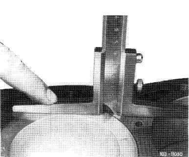
12 Measure distance between piston crown and crankcase mating surface when piston is positioned at TDC (see chart).
|
 |
||
|
|
|||
|
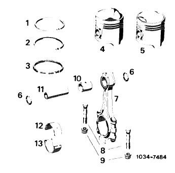
Pistons and connecting rods
|
 |
||
|
1 Plain compression ring
2 Oil scraper ring
3 Bevelled compression ring with hose lined spring
4 Piston
5 P’ston, USA and low compression
6 Circlip
7 Connecting rod with conrod cap
8 Conrod bolt
9 Nut
10 Conrod bushing
11 Conrod pin
12 Conrod bearing upper half with oil bore
13 Conrod bearing lower half
|
|||
|
|
|||
|
03.2-316/5 F3
|
|||
|
|
|||