Checking and adjusting valve clearance
|
|
|||||||||||||||||||||||||||||||
|
05—210 Checking and adjusting valve clearance
|
|||||||||||||||||||||||||||||||
|
|
|||||||||||||||||||||||||||||||
|
Valve clearance
|
cold engine (approx. 20 °C)
|
warm engine (60 °C ± 15 °C)
|
|||||||||||||||||||||||||||||
|
|
|||||||||||||||||||||||||||||||
|
Intake
|
0.101)
|
0.151)
|
|||||||||||||||||||||||||||||
|
|
|||||||||||||||||||||||||||||||
|
Exhaust
|
0.25
|
0.30
|
|||||||||||||||||||||||||||||
|
|
|||||||||||||||||||||||||||||||
|
’) 0.05 mm more for consistent outside temperature below —20 °C.
|
|||||||||||||||||||||||||||||||
|
|
|||||||||||||||||||||||||||||||
|
|||||||||||||||||||||||||||||||
|
|
|||||||||||||||||||||||||||||||
|
Valve adjusting wrench 17 mm
|
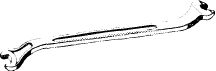 |
110 589 00 01 00
|
|||||||||||||||||||||||||||||
|
|
|||||||||||||||||||||||||||||||
|
Valve adjusting wrench 17 mm, 1/2″ square, for checking torque of adjusting screw
|
 |
110 589 00 01 00
|
|||||||||||||||||||||||||||||
|
|
|||||||||||||||||||||||||||||||
|
Slip gauge
|
 |
617 589 00 40 00
|
|||||||||||||||||||||||||||||
|
|
|||||||||||||||||||||||||||||||
|
Slip gauge blades
|
0.10 mm thick 0.15 mm thick 0.20 mm thick 0.25 mm thick 0.30 mm thick
|
617 589 00 23 00 617 589 01 23 00 117 589 00 23 00 117 589 01 23 00 617 589 02 23 00
|
|||||||||||||||||||||||||||||
|
|
|||||||||||||||||||||||||||||||
|
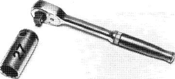
Socket wrench insert 27 mm, 1/2″ square
|
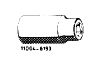 |
001 589 65 09 00
|
|||||||||||||||||||||||||||||
|
|
|||||||||||||||||||||||||||||||
|
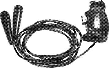
Contact grip to turn engine (part of compression recorder 001 589 46 21 00)
|
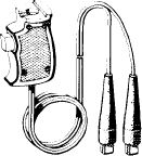 |
001 589 46 21 08
|
|||||||||||||||||||||||||||||
|
|
|||||||||||||||||||||||||||||||
|
05.2-210/1 F3
|
|||||||||||||||||||||||||||||||
|
|
|||||||||||||||||||||||||||||||
|
|
||||
|
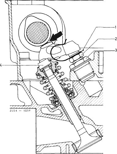
Note
Check and adjust valve clearance of cold or warm engine.
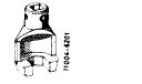
Install a thinner pressure pad (4) if the room for adjustment is no longer sufficient. Pressure pads are available in thicknesses of 2.5, 3.5 and 4.5 mm.
Attention!
The torque of easy going valve adjusting screws (2) must be checked. This requires removing all spring clamps (1) with a screwdriver and checking the torque with a valve adjusting wrench, part number 110 589 00 01 00, and a torque wrench (e. g. part number 000 589 27 21). If the torque of the valve adjusting screw is less than 20 Nm (2 kpm), replace valve adjusting screw (2) or threaded bushing (3) with valve adjusting screw (2).
|
||||
|
|
||||
|
1 Spring clamp
2 Valve adjusting screw
|
3 Threaded bushing
4 Pressure pad
 |
|||
|
|
||||
|
Adjusting valve clearance
|
 |
|||
|
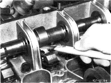
1 Remove rubber seals.
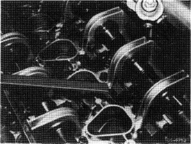
2 Check valve clearance between rocker arm and camshaft, whereby the cam peak must be up.
The valve clearance is correctly adjusted, if the slip gauge fits tight when pulled through.
|
||||
|
|
||||
|
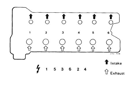
3 Note layout of intake and exhaust valves.
|
 |
|||
|
|
||||
|
05.2-210/2 F3
|
||||
|
|
||||
|
|
||||
|
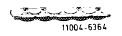
The engine can be turned as follows:
a) with the combination tool at front end of crankshaft.
|
 |
|||
|
|
||||
|
I100-64SS/S
|
||||
|
|
||||
|
b) with the starter and contact grip.
|
||||
|
|
||||
|
Models 107, 114 and 116
Connect contact grip to battery plus and terminal 50 to starter.
Disconnect cable on ignition coil terminal 1.
|
 |
|||
|
|
||||
|
105-9061
|
||||
|
|
||||
|
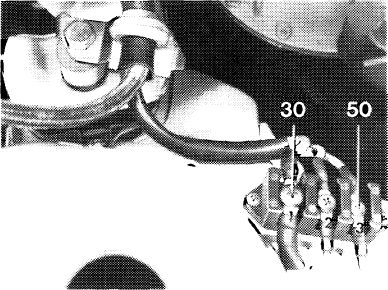
Model 123
Connect contact grip to terminal 30 and terminal 50 to wire connector.
Disconnect cable on ignition coil terminal 1.
|
\\ 100-11048
|
|||
|
|
||||
|
Disconnect fuel pump relay (3) of engines with continuous fuel injection.
|
 |
154-11205
|
||
|
|
||||
|
05.2-210/3 F3
|
||||
|
|
||||
|
|
|||
|
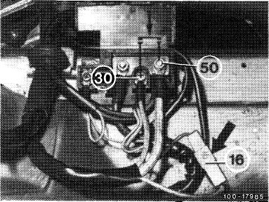
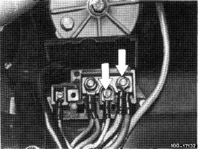
Model 126
Separate cable plug (terminal 16, arrow) so that ignition coil and on engines with CIS the fuel pump cannot be activated.
|
 |
||
|
|
|||
|
Connect terminals designated with arrows.
|
 |
||
|
|
|||
|
4 Adjust valve clearance by turning the valve adjusting screw with a valve adjusting wrench.
5 Check spring clamps for perfect fit.
6 Check seals, replacing if necessary.
|
 |
||
|
|
|||
|
05.2-210/4 F3
|
|||
|
|
|||