Static balancing of flywheel
|
|
|||||
|
03—440 Static balancing of flywheel
|
|||||
|
|
|||||
|
Data
|
|||||
|
|
|||||
|
Flywheel for
|
Balance bores
max. drilling depth Drill dia.
|
Hole locating dia.
|
|||
|
|
|||||
|
manual transmission
|
20+ 1
|
||||
|
|
|||||
|
11
|
251
|
||||
|
|
|||||
|
automatic transmission
|
drilled through
|
||||
|
|
|||||
|
Special tool
|
|||||
|
|
|||||
|
Balancing mandrel (flywheel for automatic and manual transmissions)
|
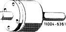 |
617 589 00 63 00
|
|||
|
|
|||||
|
Conventional tool
|
|||||
|
|
|||||
|
Rolling device for static balancing
|
Trebel, D-4030 Ratingen
type EO, order no. 03600/0904/E 0010
|
||||
|
|
|||||
|
Note
|
|||||
|
|
|||||
|
Crankshaft, balance disc and flywheel are balanced together.
A new flywheel must be balanced to the same value of the one removed.
The balancing condition of a flywheel for manual transmission can be transferred to a flywheel for automatic transmission by static balancing (and vice versa).
|
|||||
|
|
|||||
|
Static balancing
|
|||||
|
|
|||||
|
1 Place old and new flywheels on top of each other that all bores align and both clutch surfaces face in one direction.
2 Transfer mark from old to new flywheel.
|
|||||
|
|
|||||
|
03.2-440/1 F2
|
|||||
|
|
|||||
|
|
|||
|
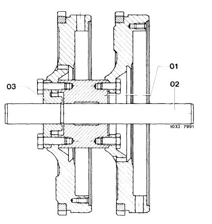
3 Apply balancing mandrel and bolt new flywheel with an offset of exactly 180° over old unit.
|
 |
||
|
01 Mounting fixture
02 Shaft
03 Centering disc
|
|||
|
|
|||
|
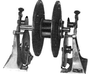
4 Let balancing mandrel with both flywheels oscillate on rolling device.
|
 |
||
|
|
|||
|
103-10648
|
|||
|
|
|||
|
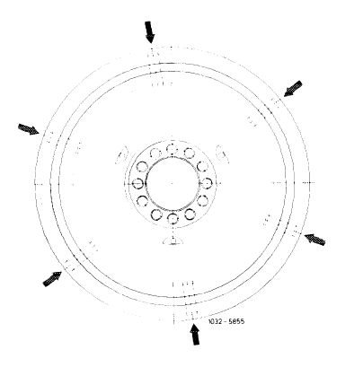
5 If an unbalance is found, drill so many holes in mass of new flywheel until the flywheels remain still without oscillating in any position.
Attention!
The hole circle dia, the drill dia and the max drilling depth must be maintained (refer to table).
The dust bores (arrows) must not be drilled.
|
 |
||
|
|
|||
|
03.2-440/2 F2
|
|||
|
|
|||