Replacing threaded bushing and valve adjusting screw
|
|
|||||||||||||||||||||||||||||||||||
|
05—212 Replacing threaded bushing and valve adjusting screw
|
|||||||||||||||||||||||||||||||||||
|
|
|||||||||||||||||||||||||||||||||||
|
Valve clearance
|
Cold engine (approx. 20 °C)
|
Warm engine (60 °C ± 15°C)
|
|||||||||||||||||||||||||||||||||
|
|
|||||||||||||||||||||||||||||||||||
|
Intake
|
0.101)
|
0.151)
|
|||||||||||||||||||||||||||||||||
|
|
|||||||||||||||||||||||||||||||||||
|
Exhaust
|
0.25
|
0.30
|
|||||||||||||||||||||||||||||||||
|
|
|||||||||||||||||||||||||||||||||||
|
0.05 mm more for consistent outside temperatures below —20 °C.
|
|||||||||||||||||||||||||||||||||||
|
|
|||||||||||||||||||||||||||||||||||
|
|||||||||||||||||||||||||||||||||||
|
|
|||||||||||||||||||||||||||||||||||
|
Depressor for valve spring
|
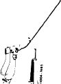 |
110 589 04 61 00
|
|||||||||||||||||||||||||||||||||
|
|
|||||||||||||||||||||||||||||||||||
|
cm
|
|||||||||||||||||||||||||||||||||||
|
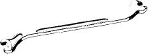
Valve adjusting wrench 17 mm, 1/2″ square, for checking torque of adjusting screw
|
 |
110 589 00 01 00
|
|||||||||||||||||||||||||||||||||
|
OS
|
|||||||||||||||||||||||||||||||||||
|
|
|||||||||||||||||||||||||||||||||||
|
Valve adjusting wrench 17 mm
|
11004-7003
|
110 589 01 01 00
|
|||||||||||||||||||||||||||||||||
|
|
|||||||||||||||||||||||||||||||||||
|
Contact grip to turn engine (part of compression recorder 001 589 46 21 00)
|
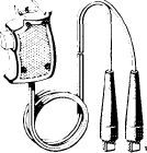 |
001 589 46 21 08
|
|||||||||||||||||||||||||||||||||
|
|
|||||||||||||||||||||||||||||||||||
|
05.2-212/1 F3
|
|||||||||||||||||||||||||||||||||||
|
|
|||||||||||||||||||||||||||||||||||
|
|
|||
|
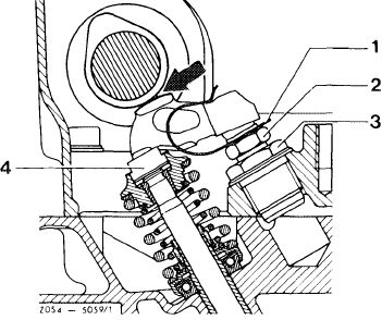
Note
If torque of valve adjusting screw is less than 20 Nm (2 kpm), replace valve adjusting screw (2) or threaded bushing (3) with valve adjusting screw (2).
|
 |
||
|
1 Spring clamp
2 Valve adjusting screw
3 Threaded bushing
4 Pressure pad
|
|||
|
|
|||
|
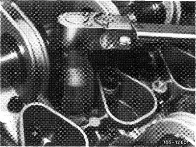
The torque can be checked with a valve adjusting wrench, part number 110 589 00 01 00 and a torque wrench (e. g. part number 000 589 27 21).
|
 |
||
|
|
|||
|
Replacing
|
 |
||
|
1 Remove rocker arms (05—230).
|
|||
|
|
|||
|
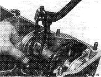
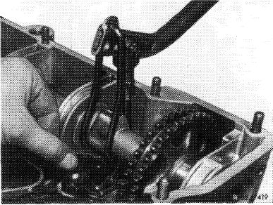
2 Unscrew threaded bushing with valve adjusting screw.
|
 |
||
|
|
|||
|
05.2-212/2
|
|||
|
|
|||
|
|
|||
|
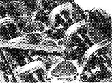
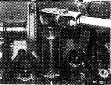
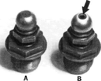
Attention!
Only use valve adjusting screws with an oil bore (arrow).
3 Coat threads of threaded bushing with valve adjusting screw with tallow, install and tighten threaded bushing to a torque of 80 Nm (8 kpm).
Attention!
Threaded bushing must be free of burrs when installing, since these would find their way into the oil circuit.
|
 |
||
|
|
|||
|
105-12453
|
|||
|
|
|||
|
4 Install rocker arms (05-230).
|
 |
||
|
|
|||
|
5 Adjust valve clearance (05—210).
|
V. 7
|
||
|
|
|||
|
05.2-212/3
|
|||
|
|
|||