Adjusting choke
|
|
||||||||||||||||||||||||||||||||||||||||||||||||||||||||
|
07.2-125 Adjusting choke
|
||||||||||||||||||||||||||||||||||||||||||||||||||||||||
|
|
||||||||||||||||||||||||||||||||||||||||||||||||||||||||
|
Testing and adjusting values
|
||||||||||||||||||||||||||||||||||||||||||||||||||||||||
|
|
||||||||||||||||||||||||||||||||||||||||||||||||||||||||
|
Carburetor without thermostatically controlled bypass choke (TN choke)
|
||||||||||||||||||||||||||||||||||||||||||||||||||||||||
|
|
||||||||||||||||||||||||||||||||||||||||||||||||||||||||
|
||||||||||||||||||||||||||||||||||||||||||||||||||||||||
|
|
||||||||||||||||||||||||||||||||||||||||||||||||||||||||
|
Only in combination with choke cover-stepped heater.
|
||||||||||||||||||||||||||||||||||||||||||||||||||||||||
|
|
||||||||||||||||||||||||||||||||||||||||||||||||||||||||
|
Carburetor with thermostatically controlled bypass choke (TN choke)
|
||||||||||||||||||||||||||||||||||||||||||||||||||||||||
|
|
||||||||||||||||||||||||||||||||||||||||||||||||||||||||
|
||||||||||||||||||||||||||||||||||||||||||||||||||||||||
|
|
||||||||||||||||||||||||||||||||||||||||||||||||||||||||
|
TN mixture
|
0.5-0.6 % CO
|
|||||||||||||||||||||||||||||||||||||||||||||||||||||||
|
|
||||||||||||||||||||||||||||||||||||||||||||||||||||||||
|
Warming-up total mixture
|
7-8% CO1)
|
|||||||||||||||||||||||||||||||||||||||||||||||||||||||
|
|
||||||||||||||||||||||||||||||||||||||||||||||||||||||||
|
TN control piston overlap at + 85 °C coolant temperature
|
0.8-1.0 mm
|
|||||||||||||||||||||||||||||||||||||||||||||||||||||||
|
|
||||||||||||||||||||||||||||||||||||||||||||||||||||||||
|
Vacuum governor adjusting data
|
Engine speed Vacuum hose pulled off
|
1700-1900
|
||||||||||||||||||||||||||||||||||||||||||||||||||||||
|
|
||||||||||||||||||||||||||||||||||||||||||||||||||||||||
|
Driving position engaged
|
600-700
|
|||||||||||||||||||||||||||||||||||||||||||||||||||||||
|
|
||||||||||||||||||||||||||||||||||||||||||||||||||||||||
|
On vehicles with draw-off for accelerating pump, adjust to lower tolerance value.
|
||||||||||||||||||||||||||||||||||||||||||||||||||||||||
|
|
||||||||||||||||||||||||||||||||||||||||||||||||||||||||
|
07.2.2 la—125/1
|
||||||||||||||||||||||||||||||||||||||||||||||||||||||||
|
|
||||||||||||||||||||||||||||||||||||||||||||||||||||||||
|
|
||||||||||||||||||||||||||||||||||||
|
Special tools
|
||||||||||||||||||||||||||||||||||||
|
|
||||||||||||||||||||||||||||||||||||
|
Oil telethermometer
|
 |
116 589 27 21 00
|
||||||||||||||||||||||||||||||||||
|
|
||||||||||||||||||||||||||||||||||||
|
Digital tester
|
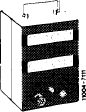 |
001 589 54 21 00
|
||||||||||||||||||||||||||||||||||
|
|
||||||||||||||||||||||||||||||||||||
|
Connecting cable 3 m long
|
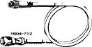 |
000 589 04 90 00
|
||||||||||||||||||||||||||||||||||
|
|
||||||||||||||||||||||||||||||||||||
|
Intermediate plug (adaptor)
|
11004-7116 %i
|
000 589 72 63 00
|
||||||||||||||||||||||||||||||||||
|
|
||||||||||||||||||||||||||||||||||||
|
Trigger
|
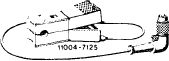 |
000 589 71 63 00
|
||||||||||||||||||||||||||||||||||
|
|
||||||||||||||||||||||||||||||||||||
|
Clamp
|
 |
000 589 40 37 00
|
||||||||||||||||||||||||||||||||||
|
|
||||||||||||||||||||||||||||||||||||
|
||||||||||||||||||||||||||||||||||||
|
|
||||||||||||||||||||||||||||||||||||
|
07.2.2 la-125/2
|
||||||||||||||||||||||||||||||||||||
|
|
||||||||||||||||||||||||||||||||||||

|
|
|||
|
A. Carburetor without thermostatically controlled bypass choke (TN choke) ©1973/74, ©1974 California
|
 |
||
|
Testing, adjusting
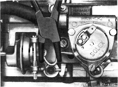
1 Remove air filter. Check whether marking notch on choke cover is exactly opposite mark on carburetor housing (arrow) and adjust choke cover, if required.
|
|||
|
|
|||
|
2 Check choke housing for tight seat, insert loose fastening screws with Omnifit or Loctite, if required.
3 Check choke valve for easy operation and make operable, if required.
Complete test with cold engine whenever possible. The choke valve and the transmitting linkage should move easily in any position. To check, disconnect choke rod, if required. If choke valve binds or is hard to move, refinish carburetor shaft laterally as required.
|
 |
||
|
|
|||
|
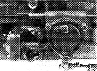
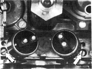
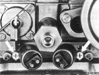
4 Check for uniform adjustment of idle speed mixture adjusting screws (arrows). For this purpose, run engine oil temperature to approx. 80 °C. Then run engine for approx. 5 min. at idle speed for stabilization.
|
 |
||
|
|
|||
|
For subsequent CO measurement, make air injection inoperative as follows (for (@) 1973/74 nothing need be made inoperative):
|
 |
||
|
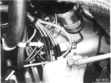
(7) 1976
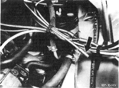
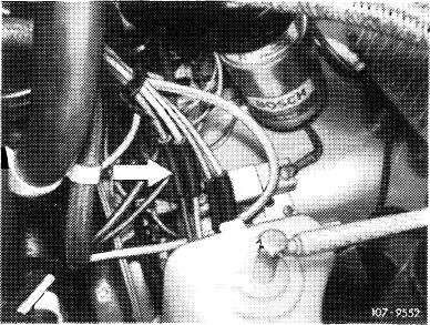
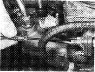
Pull off blue/purple vacuum line at connecting point (arrow).
|
|||
|
|
|||
|
07.2.2 la-125/3
|
|||
|
|
|||
|
|
|||
|
1976, model 114
|
 |
||
|
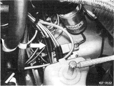
Pull rubber cap (arrow) from blue/purple vacuum line.
|
|||
|
|
|||
|
T) 1976, model 116
|
 |
||
|
Pull rubber cap (arrow) from blue/purple vacuum line.
|
|||
|
|
|||
|
(yiA) California 1974
|
 |
||
|
Pull off red vacuum line at connecting point (arrow).
|
|||
|
® 1975/76
Pull off blue/purple vacuum line at connecting point (arrow).
|
|||
|
|
|||
|
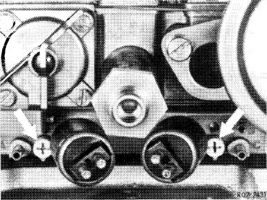
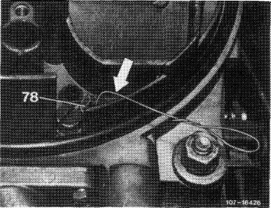
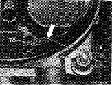
Insert test wire 0.5 mm dia. (arrow) into both air correction jets (78) one after the other and measure CO increase. The CO increase should be the same on both sides (corrections 07.2-101).
Note: To prevent measuring faults, do not insert test wire deeper than 10 mm into idle speed jet. Without test wire, the max. idle speed emission value should not be exceeded.
5 Reattach vacuum hose for air injection (air injection operating).
|
 |
||
|
|
|||
|
07.2.2 la-125/4
|
|||
|
|
|||
|
|
|||
|
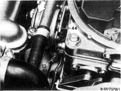
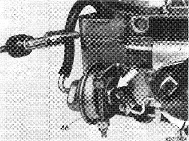
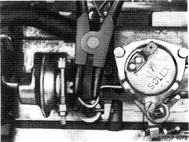
6 Adjust choke valve gap. For this purpose, run engine at idle speed until the vacuum has pulled the diaphragm in dashpot (46) completely back against stop (arrow). Then pinch vacuum hose.
|
 |
||
|
Choke housing version 1 (sheet rnetal pulldown)
|
|||
|
|
|||
|
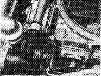
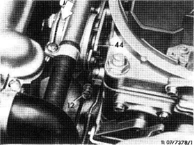
Slightly actuate throttle valve lever and push fast idle cam (44) upwards against stop. Release throttle valve lever.
|
 |
||
|
|
|||
|
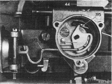
Insert wire hook (195) through slot in choke housing to push drive lever (194) of bimetallic spring up to noticeable stop.
Attention!
Do not push drive lever too heavily against stop, since otherwise the diaphragm will be pulled back and
measuring faults will result.
|
 |
||
|
Starter housing version 1 (sheet metal pulldown)
|
|||
|
|
|||
|
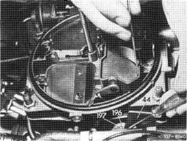
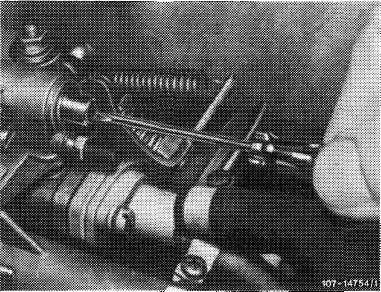
Push drive lever (196) up to noticeable stop by means of a screwdriver.
Measure choke valve gap between downward-opening wing of choke valve and measure carburetor wall.
Note: To eliminate any play in linkage, make sure that the measuring plug enters tightly.
|
 |
||
|
Choke housing version 2 (cast iron starter housing)
|
|||
|
|
|||
|
07.2.2 la-125/5
|
|||
|
|
|||
|
|
|||
|
Adjust choke valve gap by bending connecting rod between automatic choke and dashpot as required.
Pushing apart = decreasing gap Pushing together = increasing gap
|
 |
||
|
Decreasing choke valve gap
|
|||
|
|
|||
|
Increasing choke valve gap
|
 |
||
|
|
|||
|
Adjust choke valve gap by turning choke valve gap adjusting screw in choke housing cover.
Screwing in = decreasing gap Screwing out = increasing gap
Attention!
If choke valve gap changes during adjustment, check pulldown for leaks, since the O-ring in pulldown cover might be leaking.
|
 |
||
|
Adjusting choke valve gap (cast iron choke housing)
|
|||
|
|
|||
|
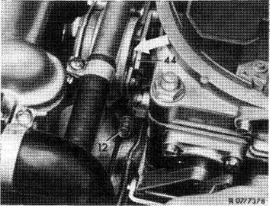
7 Adjust cold starting speed. For this purpose, run engine at operating temperature (60—80 °C engine oil temperature). Slightly lift throttle valve lever and push fast idle cam (44) upwards against stop. Release throttle valve lever. Measure engine speed and adjust with adjusting screw (12), if required.
|
 |
||
|
|
|||
|
07.2.2 la-125/6
|
|||
|
|
|||
|
|
|||
|
B. Carburetor with thermostatically controlled bypass choke (TN choke)
|
|||
|
|
|||
|
Note
|
|||
|
|
|||
|
To obtain perfect starting and warming-up characteristics, the tests and adjustments described here should be performed with great care. It is particularly important that all CO measurements are made without air injection and EGR, as well as without draw-off for accelerating pump, if installed. The CO tester should be in perfect condition. CO value should be balanced well.
|
|||
|
|
|||
|
Testing, adjusting
|
 |
||
|
1 Remove air filter. Check whether marking notch on choke cover is located accurately opposite mark on carburetor housing (arrow) and adjust choke cover, if required.
|
|||
|
|
|||
|
2 Check choke housing for tight seat and insert any loose fastening screws with Omnifit or Loctite.
|
 |
||
|
|
|||
|
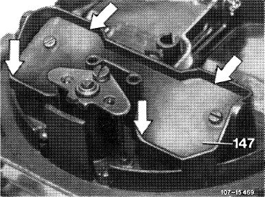
3 Check choke valve (147) for easy operation and make operable, if required.
Complete test on cold engine whenever possible. The choke valve and the transmitting linkage should be easily moving in any position. To check, disconnect choke rod, if required. If choke valve binds or is hard to move, refinish carburetor shaft accordingly.
|
 |
||
|
|
|||
|
07.2.2 la-125/7
|
|||
|
|
|||
|
|
|||
|
4 Run engine oil temperature to approx. 80 °C.
5 Check pulldown delay.
Note: If the delay is too long, the mixture is made leaner too slowly after starting and the spark plugs may soot up and fail. If the delay is too short, the mixture is made leaner too fast and the engine develops a trend towards stalling.
|
|||
|
|
|||
|
a) Testing switchover valve for pulldown delay
For this purpose, pull high-voltage cable 4 out of distributor cover and connect to ground.
|
|||
|
|
|||
|
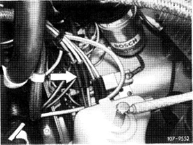
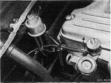
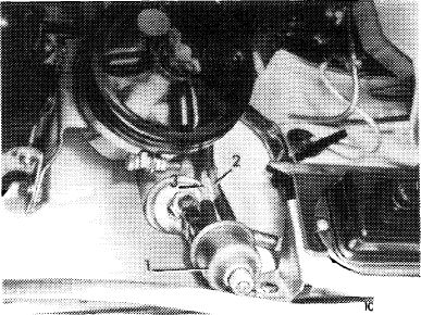
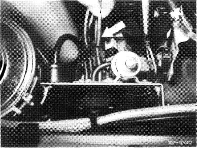
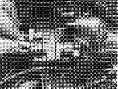
Actuate starter several times for short periods. Switching procedure of switchover valve (1) should be heard or felt.
Pull red vacuum line (2) from switchover valve and connect vacuum tester to valve. Actuate starter, tester should indicate no vacuum (switchover valve switches vacuum to atmosphere).
|
I7-9622
|
||
|
Model 114
|
|||
|
|
|||
|
Plug high-voltage cable 4 in again. Run engine, tester should now indicate a vacuum (switchover valve connects vacuum to pulldown).
Note: The vacuum on tester is indicated under delay, under influence of throttle jet in connecting pipe for vacuum.
|
 |
||
|
Model 116
|
|||
|
|
|||
|
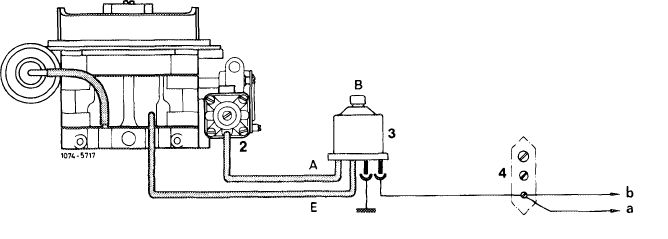
1 Solex carburetor 4 A 1
2 Choke housing
3 Switchover valve
4 Cable connector
|
|||
|
|
|||
|
A Outlet (to choke housing — red line)
B Vent (to atmosphere)
E Inlet (from carburetor — white line)
a To ignition starter switch
b To starter terminal 50
 |
|||
|
|
|||
|
07.2.2 la-125/8
|
|||
|
|
|||
|
|
|||
|
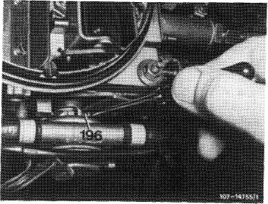
b) Checking thermo delay valve
With the engine running, pull off vacuum hose for pulldown on throttle valve section. Plug vacuum hose in again while simultaneously measuring the time up to the moment when choke valve is not opening any further. The delay should amount to 5—12 seconds.
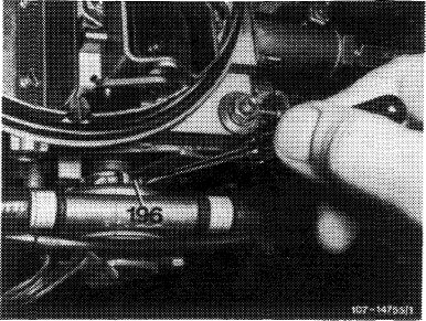
After attaching vacuum hose, wait for approx. 4—5 seconds, then push lever (196) lightly against stop. (If the idle speed drops, stop checkup and start again to avoid faulty measurements).
Yielding to counterpressure of pulldown now becoming effective on lever (196), watch until the choke valve stops opening any further. If the delay period is not the result of the tolerance, check pulldown throttle for passage and pulldown itself for leaks.
|
 |
||
|
|
|||
|
c) Checking pulldown throttle
For this purpose, remove thermo delay valve together with vacuum hoses. Plug the longer of the removed vacuum hoses to pulldown. Run engine and plug vacuum hose to throttle valve member. After max. 3 seconds, push lever (196) up to noticeable stop, the choke valve should now be at gap width. If not, clean throttle and replace, if required. Repeat checkup.
|
 |
||
|
|
|||
|
6 Check pulldown for leaks. For this purpose, pinch vacuum hose with a clamp while the engine is running, then stop engine and push choke valve to gap width; width of choke valve gap should not decrease, if it does, the pulldown is leaking. Replace pulldown cover ■ r diaphragm, if required.
If the pulldown is sealed well and the throttle passage is in order, replace thermo delay valve.
|
 |
||
|
|
|||
|
07.2.2 la-125/9
|
|||
|
|
|||
|
|
|||
|
7 Check for uniform adjustment of idle speed mixture adjusting screws (arrows). For this purpose, run engine oil temperature up to approx. 80 °C. Permit approx. one minute for CO indication to come to rest.
|
 |
||
|
|
|||
|
Perform the following CO measurements without air injection and without EGR. Make air injection inoperative as follows:
|
 |
||
|
(V) 1976
Pull off blue/purple vacuum line at connecting point (arrow).
|
|||
|
|
|||
|
1976, model 114
|
 |
||
|
Pull rubber cap (arrow) from blue/purple vacuum line.
|
|||
|
|
|||
|
® 1976, model 116
Pull rubber cap (arrow) from blue/purple vacuum line.
|
 |
||
|
|
|||
|
07.2.2 la-125/10
|
|||
|
|
|||
|
|
|||
|
(usa) 1975/76
Pull off blue/purple vacuum line at connecting point (arrow).
|
 |
||
|
|
|||
|
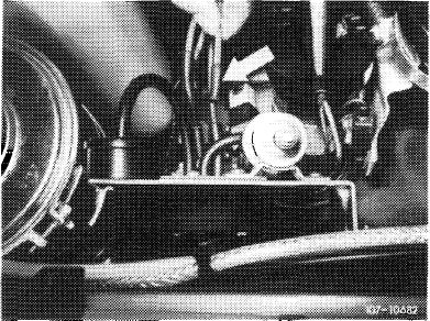
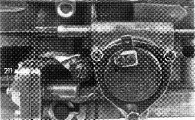
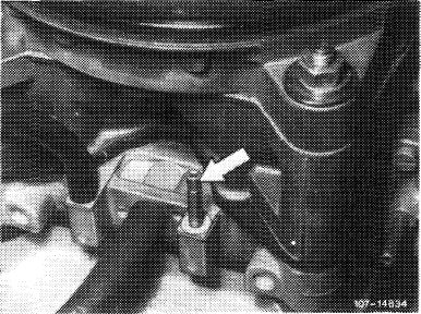
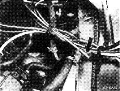
The exhaust gas for idle speed CO measurement on vehicles with catalyst, (T) 1976 and (usa) 1975/76 is drawn off in front of catalyst at check valve (arrow) of air injection.
|
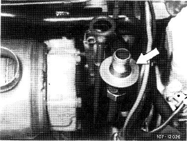 |
||
|
|
|||
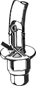
|
For measuring idle speed emissions, open valve plate of check valve by means of a self-made wire hook. Connect exhaust gas hose of CO measuring instrument to check valve.
|
 |
||
|
|
|||
|
1074-6964
|
|||
|
|
|||
|
Insert test wire 0.5 mm dia. (arrow) into both air correction jets (78) one after the other and measure CO increase. The CO increase should be the same on both sides (corrections 07.2-101).
Note: To prevent measuring faults, do not insert test wire for more than 10 mm into idle speed air jet. Without test wire, the max. idle speed emission value should not be exceeded.
|
 |
||
|
|
|||
|
07.2.2 la—125/11
|
|||
|
|
|||
|
|
|||
|
8 Check TN mixture and adjust. For this purpose, run engine oil temperature to approx. 80 °C. Then run engine for approx. five minutes to stabilize at idle.
Set idle speed emission value accurately to 1.0 % CO
by uniform adjustment of adjusting screws (arrows).
Screwing in = leaner Screwing out = richer
Attention!
Wait for approx. one minute to let CO values come to rest to avoid measuring faults. CO measurements should be taken and adjustments made at approximately the same engine oil temperature and, if installed, without drawing off at accelerating pump.
|
 |
||
|
|
|||
|
Remove thermostatically controlled bypass choke (TN choke) with water hoses connected and put aside. Then install TN test choke (self-made, refer to end of chapter) with gasket in such a manner that the bores are facing upwards.
|
 |
||
|
|
|||
|
Pull off hose for drawing off at accelerating pump, if installed, and close draw-off connection on TN choke duct. With the engine running and the choke valve completely open, check CO value, which should amount to 0.5-0.6 %. If required, adjust by means of TN mixture adjusting screw.
Screwing in = leaner Screwing out = richer
(Below 0.5 % CO, the TN mixture is too lean, above 0.6 % it is too rich).
|
 |
||
|
|
|||
|
07.2.2 la-125/12
|
|||
|
|
|||
|
|
|||
|
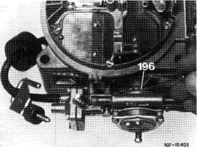
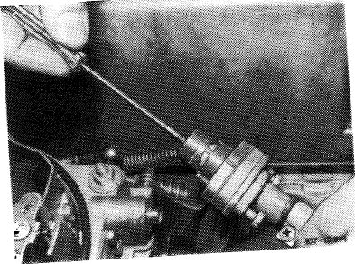
9 Check warming-up total mixture and adjust. Run engine with TN test choke installed. Push choke valve on lever (196) until noticeably stopped (choke valve gap). Check CO value and set by adjusting choke valve gap, if required.
Screwing out = leaner Screwing in = richer
Nominal value: 7—8 % CO
(On carburetors with draw-off connection for accelerating pump, set to low CO value).
|
 |
||
|
|
|||
|
Note: If the adjusting screw is suddenly moving easily during adjustment, the O-ring is defective. In such a case, make sure to check pulldown once again for leaks.
|
 |
||
|
Adjusting warming-up total mixture
|
|||
|
|
|||
|
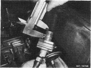
10 Check TN control piston position at 85 °C coolant temperature and adjust. For this purpose, run engine with TN test choke installed. Measure dimension „X” form face to upper edge of control window directly adjacent to web.
|
 |
||
|
Measure dimension „X”
|
|||
|
|
|||
|
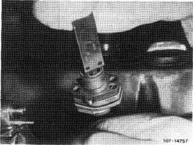
Then measure dimension „Y” from face to edge of control piston.
Dimension „Y” should be 0.8-1.0 mm smaller than dimension „X”, so that the control piston closes the control window with overlap.
Control piston overlap: at 85 °C coolant temperature 0.8-1.0 mm.
|
 |
||
|
Measure dimension „Y”
|
|||
|
|
|||
|
07.2.2 la-125/13
|
|||
|
|
|||
|
|
|||
|
Setting control piston position by means of adjusting screw.
Screwing out – reducing overlap Screwing in – increasing overlap
Note- At + 20 °C temperature of TN choke the TN „tofwindow shou.d be open by a, least 2.5 -. At each 10 °C change in temperature, the control Ion travels a distance of approx. 0.5 mm …. at appro* 70 °C coolant temperature the control window is i-. Cosed. At approx. 0 °C control window is completely open.
|
 |
||
|
|
|||
|
1, Remove TN test choke and re-install TN choke
put aside earlier.
12 Check idle speed and idle speed emission value
and adjust, if required.
Nnt*- If the idle speed emission value is within the
ces the warming-up total mixture.
13 Plug-in again vacuum line for air injection and EGR (air injection and EGRoperat.ve).
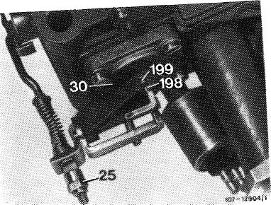
14 Check accelerating pump and adjust, if required (67.2-150).
|
 |
||
|
|
|||
|
25 Adjusting nut in accelerating pump
|
|||
|
|
|||
|
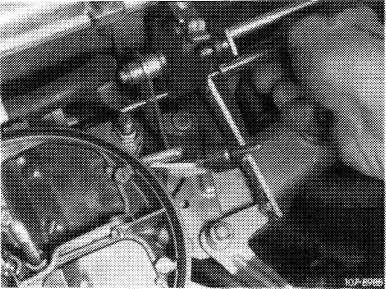
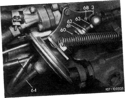
! 5 Adjust vacuum governor. For this purpose run ^U^v^umho«(64)ij«to^-d speed by means of adjusting screw (63), plug on vacuum hose.
Wh” looting counters apply countered to diaphragm rod.
|
 |
||
|
|
|||
|
07.2.2 la-125/14
|
|||
|
|
|||
|
|
|||
|
On automatic transmission, engage driving position, set to specified speed by means of adjusting nut (61). Turn power steering to full lock and engage air conditioner, engine should still run smoothly. Readjust speed, if required.
|
|||
|
|
|||
|
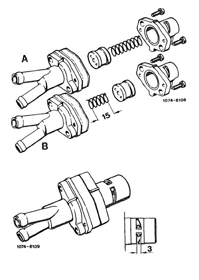
Self-made TN test choke
|
 |
||
|
16 Unscrew the two fastening screws for the TN piston housing and remove piston housing.
17 Coat control piston with Omnifit or Loctite and slip back into piston housing with open side first. Shorten compression spring to approx. 15 mm, mount and tighten piston housing.
|
|||
|
18 Then drill two 3 mm holes through TN control piston.
|
|||
|
|
|||
|
07.2.2 la-125/15
|
|||
|
|
|||
<<< Back