Testing starting device (choke) for function (cold start)
|
|
||||||||||||||||||||||||||||||||
|
07.2—128 Testing starting device (choke) for function (cold start)
|
||||||||||||||||||||||||||||||||
|
|
||||||||||||||||||||||||||||||||
|
Testing and adjusting values
|
||||||||||||||||||||||||||||||||
|
|
||||||||||||||||||||||||||||||||
|
||||||||||||||||||||||||||||||||
|
|
||||||||||||||||||||||||||||||||
|
Terminal 15
|
3.6-4.6
|
|||||||||||||||||||||||||||||||
|
|
||||||||||||||||||||||||||||||||
|
Breaker contact „closed”
|
||||||||||||||||||||||||||||||||
|
|
||||||||||||||||||||||||||||||||
|
Terminal 1
|
0.7-1.5
|
|||||||||||||||||||||||||||||||
|
|
||||||||||||||||||||||||||||||||
|
Terminal 15
|
battery voltage
|
|||||||||||||||||||||||||||||||
|
|
||||||||||||||||||||||||||||||||
|
Breaker contact „open’
|
||||||||||||||||||||||||||||||||
|
|
||||||||||||||||||||||||||||||||
|
Terminal 1
|
battery voltage
|
|||||||||||||||||||||||||||||||
|
|
||||||||||||||||||||||||||||||||
|
Voltage at pre-resistor
|
||||||||||||||||||||||||||||||||
|
|
||||||||||||||||||||||||||||||||
|
Pre-resistor output 0.4 ohm Cable: red/black (Pre-resistor bridge-over)
|
min. 9.6 volts
|
|||||||||||||||||||||||||||||||
|
|
||||||||||||||||||||||||||||||||
|
Carburetor
|
||||||||||||||||||||||||||||||||
|
|
||||||||||||||||||||||||||||||||
|
TN control window opening at + 20 °C
|
approx. 2.5 mm
|
|||||||||||||||||||||||||||||||
|
|
||||||||||||||||||||||||||||||||
|
CO value after starting cold engine
|
7-8 %’)
|
|||||||||||||||||||||||||||||||
|
|
||||||||||||||||||||||||||||||||
|
M If the CO value is essentially above upper tolerance, spark plugs have a tendency for sooting, engine starts misfiring. If it is considerably below lower tolerance, starting faults and bypass faults may occur.
Special tools
|
||||||||||||||||||||||||||||||||
|
|
||||||||||||||||||||||||||||||||
|
Digital tester
|
 |
001 589 54 21 00
|
||||||||||||||||||||||||||||||
|
|
||||||||||||||||||||||||||||||||
|
Connecting cable 3 m long
|
 |
000 589 04 90 00
|
||||||||||||||||||||||||||||||
|
|
||||||||||||||||||||||||||||||||
|
Intermediate plug (adaptor)
|
 |
000 589 72 63 00
|
||||||||||||||||||||||||||||||
|
|
||||||||||||||||||||||||||||||||
|
07.2.2 la—128/1
|
||||||||||||||||||||||||||||||||
|
|
||||||||||||||||||||||||||||||||
|
|
||||||
|
Trigger
|
 |
000 589 71 63 00
|
||||
|
|
||||||
|
Conventional test instruments
|
||||||
|
|
||||||
|
Voltmeter, revolution counter and CO measuring instrument
|
||||||
|
|
||||||
|
Testing
|
 |
|||||
|
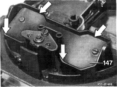
1 Let engine cool down to below + 20 °C. Check whether choke valve (147) is completely closed and has lateral clearance. (Below + 20 °C the choke valve should be completely closed).
2 Remove air filter, pull cable from choke cover heater so that choke valve is not completely opening during the following voltage measurements.
3 Check battery for external condition (visual checkup). Check battery poles for oxidation.
4 Test voltages on battery.
|
||||||
|
|
||||||
|
a) Rest potential
Connect voltmeter to battery plus and minus pole, read voltage.
Nominal value: min. 12.2 volts
|
||||||
|
|
||||||
|
b) Starting voltage
Pull high-voltage ignition cable 4 out of distributor cover and connect to ground. Operate starting motor while reading voltage.
Nominal value: min. 10 volts
|
||||||
|
|
||||||
|
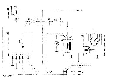
1 Ignition starter switch
2 Pre-resistor 0.4 ohm
3 Pre-resistor 0.6 ohm
4 Ignition coil
5 Standard switchgear
6 Ignition distributor
7 Diagnosis plug
a To starter terminal 16
b To diagnosis socket
|
 |
|||||
|
|
||||||
|
07.2.2 la-128/2
|
||||||
|
|
||||||
|
|
|||
|
5 Test voltages at ignition coil.
a) With breaker contact closed at terminal 15 and terminal 1:
Nominal values Terminal 15, 3.6—4.6 volts Terminal 1, 0.7—1.5 volts
b) With breaker contact opened at terminal 15 and terminal 1:
Nominal values: Terminal 15 and terminal 1 should be energized by battery voltage.
6 Measure voltage at pre-resistor 0.4 ohm while starting (pre-resistor bridge-over).
Nominal value: min. 9.6 volts
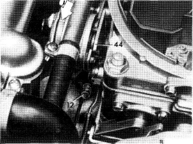
7 Insert high-voltage ignition cable 4 again into distributor cover.
|
|||
|
|
|||
|
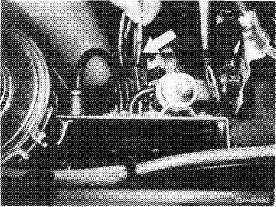
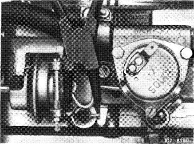
8 Check choke cover preload. Markings (arrow) should be opposite each other.
|
 |
||
|
J///J/8/1
|
|||
|
|
|||
|
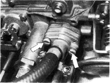
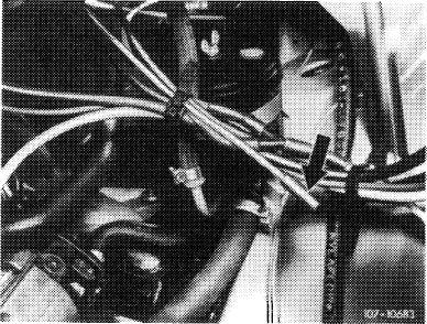
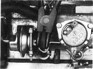
9 Remove TN choke after loosening fastening screws (arrow) together with coolant hoses.
|
W7-127B
|
||
|
|
|||
|
07.2.2 la-128/3
|
|||
|
|
|||
|
|
|||
|
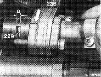
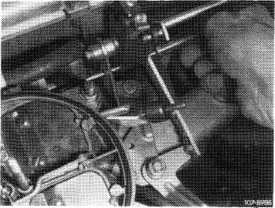
10 Measure control window opening „a” exposed by control piston with slide gauge.
Nominal values: At + 20 °C approx. 2.5 mm.
At approx. 0 °C control window should be completely open.
11 Install TN choke and air filter.
12 Check warming-up total mixture without air injection and EGR, adjust. For this purpose, connect CO measuring instrument and make air injection inoperative as described below (for (©> 1973/74 nothing need be made inoperative):
|
 |
||
|
|
|||
|
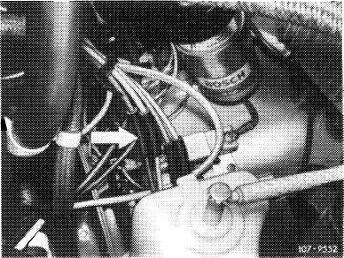
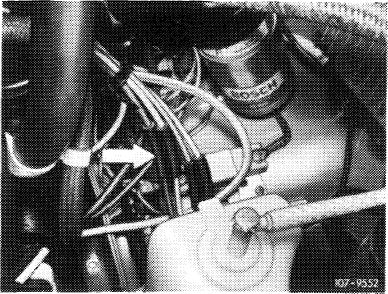
(JJ 1976
Pull off blue/purple vacuum line at connecting point (arrow).
|
 |
||
|
|
|||
|
T) 1976, model 114
|
 |
||
|
Pull rubber cap (arrow) from blue/purple vacuum line.
|
|||
|
|
|||
|
T) 1976, model 116
|
 |
||
|
Pull rubber cap (arrow) from blue/purple vacuum line.
|
|||
|
|
|||
|
07.2.2 la-128/4
|
|||
|
|
|||
|
|
|||
|
(usa) California 1974
|
 |
||
|
Pull off red vacuum line at connecting point (arrow).
|
|||
|
<©) 1975/76
Pull off blue/purple vacuum line at connecting point (arrow).
|
|||
|
|
|||
|
Start engine and rapidly depress accelerator upon firing.
Engage driving position for automatic transmission, permit CO value to come to rest and read. (If deviations from tolerance value are high, stop engine immediately, change choke valve gap accordingly and repeat CO test).
Nominal value: 7-8 % CO
|
 |
||
|
Pushing together = leaner
|
|||
|
|
|||
|
Pushing apart = richer
|
 |
||
|
|
|||
|
Screwing out = leaner Screwing in = richer
|
 |
||
|
|
|||
|
07.2.2 la-128/5
|
|||
|
|
|||
|
|
||
|
Again plug-on vacuum hoses for air injection and EGR (air injection with EGR operative).
13 Again plug-on cable for choke cover heater.
14 Test regulating voltage of alternator.
Note: Prior to testing regulating voltage, check acid density of battery. If acid density (state of charge) of battery is lower than 1.24 kg/dm3 in tropical countries, a defective transistor regulator (full regulation) is no longer recognized.
Checkup
Engine speed: 3000/min
Battery load: Compulsory consumer only (ignition) Regulating voltage measured after approx. two minutes: 13.0-14.5 volts.
|
||
|
|
||
|
07.2.2 la-128/6
|
||
|
|
||