Regulation of engine
|
|
|||||
|
07.2—110 Regulation of engine
|
|||||
|
|
|||||
|
Identification: Information plate in national language on cross member in front of radiator or on cylinder head cover. Adjust engines according to data of respective emission control information plate.
|
|||||
|
|
|||||
|
Testing and adjusting values
|
|||||
|
|
|||||
|
National version
|
Idle speed 1/min
|
Idle speed emission value % CO
|
|||
|
|
|||||
|
up to 1976
|
max. 1.5
|
||||
|
|
|||||
|
1976
|
800-900
|
||||
|
|
|||||
|
max. 1.0 without air injection
|
|||||
|
|
|||||
|
1976
|
|||||
|
|
|||||
|
1973
|
|||||
|
|
|||||
|
750-900
|
up to 1.5
|
||||
|
|
|||||
|
1974 Federal
|
|||||
|
|
|||||
|
(usa) 1974 California
|
700-900
|
6—8 without air injection
|
|||
|
|
|||||
|
1975/76
|
800-900
|
max. 1.0 without air injection
|
|||
|
|
|||||
|
Vacuum governor1)
|
|||||
|
|
|||||
|
National version
|
Engine speed
Vacuum hose pulled off
1/min
|
Engine speed
Driving position engaged
1/min
|
|||
|
|
|||||
|
without
TN choke
|
with
TN choke
|
||||
|
|
|||||
|
1976
|
|||||
|
|
|||||
|
1976
|
600-700
|
||||
|
|
|||||
|
1700-1900
|
|||||
|
|
|||||
|
1973/74
|
1200-1400
|
||||
|
|
|||||
|
1975/76
|
|||||
|
|
|||||
|
M When engaging all auxiliary units, the engine should still run smoothly.
|
|||||
|
|
|||||
|
07.2.2 la—110/1
|
|||||
|
|
|||||
|
|
||||
|
Accelerating pump
|
||||
|
|
||||
|
Begin of injection
|
immediately
|
|||
|
|
||||
|
Special tools
|
||||
|
|
||||
 |
||||
|
|
||||
|
Oil telethermometer
|
116 589 27 21 00
|
|||
|
|
||||
|
Digital tester
|
 |
001 589 54 21 00
|
||
|
|
||||
|
us£S: m
|
||||
|
|
||||
|
Connecting cable 3 m long
|
000 589 04 90 00
|
|||
|
|
||||
|
Intermediate plug (adaptor)
|
 |
000 589 72 63 00
|
||
|
|
||||
|
Trigger
|
 |
000 589 71 63 00
|
||
|
|
||||
|
Clamp
|
000 589 40 37 00
|
|||
|
|
||||
|
Conventional tools
|
||||
|
|
||||
|
Closing angle (dwell angle) and revolution counter, stroboscope, oscilloscope, CO measuring instrument
|
||||
|
|
||||
|
Note
|
||||
|
|
||||
|
Do not adjust idle speed when engine is too hot, e.g. after a fast drive or after measuring performance on a dynamometer. The air filter should be mounted.
|
||||
|
|
||||
|
07.2.2 la-110/2
|
||||
|
|
||||
|
|
|||
|
Regulation
|
 |
||
|
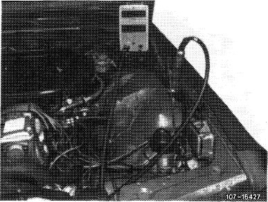
1 Connect test instruments:
• Closing angle and revolution counter
• Stroboscope
• Oscilloscope
• CO measuring instrument
• Digital tester
2 Check contact resistance, closing angle and closing angle change, adjust closing angle only when renewing contact breaker points (07.5—510).
3 Evaluate oscilloscope display.
4 Check firing point and adjust, if required. Check centrifugal and vacuum ignition adjustment (07.5-510).
5 Run engine oil temperature up to 60—80 °C.
6 Check intake system for leaks. For this purpose, spray all seal points with Iso-Oktan DIN 51756 or benzine. Change of engine speed indicates leaks.
Attention!
For spraying, do not use conventional fuel (unhealthy vapors). Pay attention to inflammability and do not spray on red-hot components or components of ignition system.
7 Check engine regulating linkage for easy operation and wear. Lubricate all bearing points and ball sockets.
|
|||
 |
|||
|
|
|||
|
8 Switch off air conditioning system or automatic climate control. Move selector lever into position
|
|||
|
|
|||
|
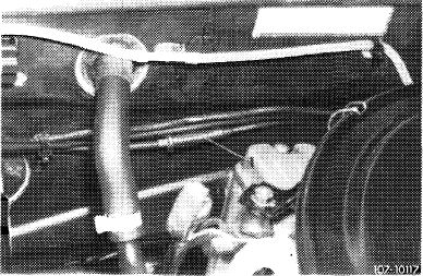
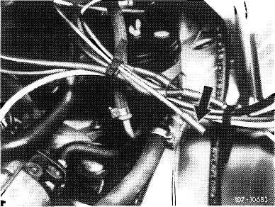
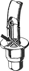
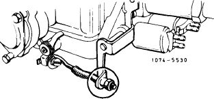
9 Check whether on vehicles with cruise control (Tempomat) the Bowden wire rests free of tension against regulating lever with the engine running. Adjust Bowden wire with adjusting nut (1), if required. For this purpose, run engine.
|
 |
||
|
|
|||
|
07.2.2 la—110/3
|
|||
|
|
|||
|
|
|||
 |
|||
|
|
|||
|
10 With the engine running, check whether throttle valve lever (3) rests against adjusting screw (68).
11 Check idle speed and adjust with adjusting screw (68), if required.
|
 |
||
|
|
|||
|
12 Check idle speed emission value without air injection. For this purpose, make air injection inoperative as follows (for (usa) 1973/74 nothing need be made inoperative):
|
 |
||
|
(T) 1976
Pull off blue/purple vacuum line at connecting point (arrow).
|
|||
|
|
|||
|
1976, model 114
|
 |
||
|
Pull rubber cap (arrow) from blue/purple vacuum line.
|
|||
|
|
|||
|
07.2.2 la—110/4
|
|||
|
|
|||
|
|
|||
|
T) 1976, model 116
|
 |
||
|
Pull rubber cap (arrow) from blue/purple vacuum line.
|
|||
|
|
|||
|
(usa) California 1974
Pull off red vacuum line at the connecting point (arrow).
|
 |
||
|
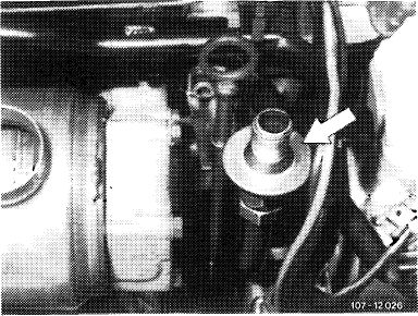
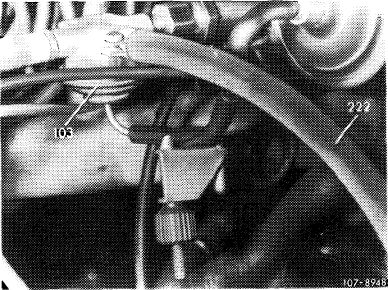
(©) 1975/76
Pull off blue/purple vacuum line at connecting point (arrow).
|
|||
|
|
|||
|
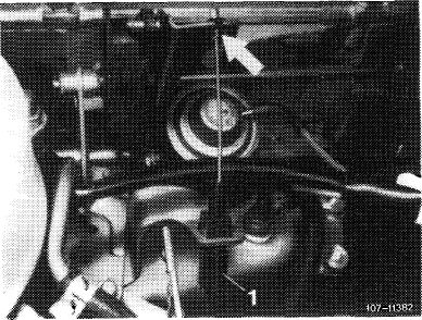
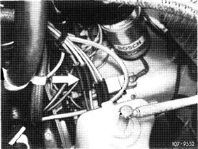
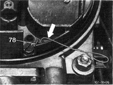
The exhaust gas for idle speed CO measurement on vehicles with catalyst, (T)i976and ©)1975/76, is drawn off in front of catalyst at check valve (arrow) of air injection.
|
 |
||
|
|
|||
|
For measuring idle speed emissions, open valve plate of check valve by means of a self-made wire hook. Connect exhaust gas hose of CO measuring instrument to check valve.
|
 |
||
|
|
|||
|
W74-6964
|
|||
|
|
|||
|
07.2.2 la—110/5
|
|||
|
|
|||
|
|
|||
|
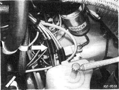
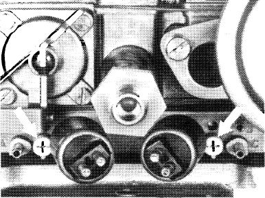
13 Adjust idle speed emission value without air injection. For this purpose, adjust both adjusting screws (arrows) uniformly.
Screwing out = richer Screwing in = leaner
|
107 7433
|
||
|
|
|||
|
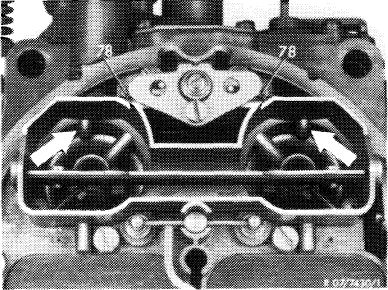
Then check idle speed synchronization while inserting test wire 0.5 mm dia (arrow) into both air correction nozzles (78) one after the other and measuring CO increase. The CO increase should be uniformly high on both sides. Readjust with idle speed mixture adjusting screws, if required.
Note: To prevent measuring faults, do not insert test wire deeper than 10 mm into idle speed air jet. Without test wire, the max. idle speed emission value may not be exceeded. Readjust uniformly, if required.
Accelerate for a short moment, check idle speed and idle speed emission value once again and regulate again, if required.
|
 |
||
|
|
|||
|
14 Reattach vacuum hose for air injection (air injection operating). The idle speed emission value should now be below the previously set value.
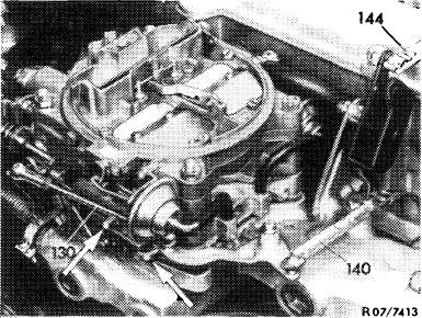
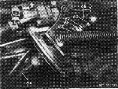
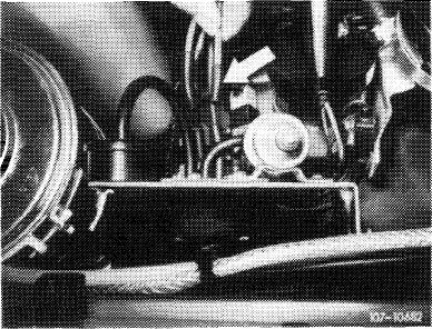
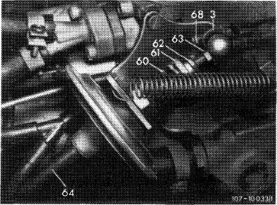
15 Adjust vacuum governor. For this purpose, run engine, pull off vacuum hose (64), adjust specified speed with adjusting screw (63), attach vacuum hose.
Attention!
When loosening counternut, apply counterhold to diaphragm rod.
Engage driving position on automatic transmission, set to specified speed with adjusting nut (61). Turn power steering to full lock and engage air conditioning system, engine should still run smoothly. Regulate speed again, if required.
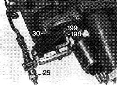
16 Adjust accelerating pump. For this purpose, run engine, pinch vacuum hose (64). Check whether throttle valve lever (3) rests against adjusting screw (68) (Fig. item 15).
Set adjusting nut (25) in such a manner that the actuating lever (198) pushes the diaphragm thrust bolt (199) 1.0 mm inwards.
|
 |
||
 |
|||
|
|
|||
|
SO?- 12904/1
|
|||
|
|
|||
|
07.2.2 la-110/6
|
|||
|
|
|||
|
|
||||
|
Starting June 1973 the adjusting nut with pinch lock is replaced by a self-locking polystop nut. Simultaneously, the connecting rod has been extended by 2 mm (to facilitate adjustments).
|
 |
|||
|
|
||||
 |
 |
|||
|
|
||||
|
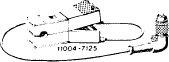
Former version
|
Present version
|
|||
|
|
||||
|
Checking operation and direction of injection.
For this purpose, slowly actuate throttle valve lever, a uniform fuel jet should now come out of both injection bores (arrows) immediately and on both sides.
Attention!
The fuel jet should not touch edge of Venturi and pre-atomizer, since this may result in starting and bypass faults. If required, remove carburetor cover and clean injection bores.
|
 |
|||
|
|
||||
|
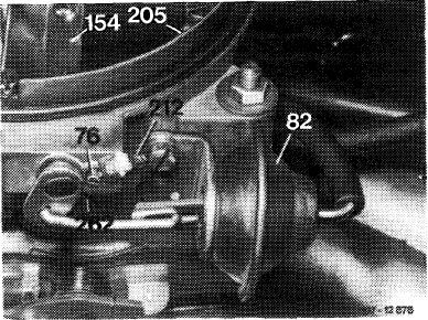
17 Check dashpot (82) for leaks. Then run engine, pinch vacuum hose of damper (82). Open air valve (154) and release, air valve should then snap back against stop (205). If not, replace dashpot. With the engine stopped, check whether air valve (154) operates easily and returns automatically to stop (205) if slightly opened.
|
 |
|||
|
82 Dashpot for air valve stage II
|
||||
|
|
||||
|
18 Check fuel return valve for leaks. For this purpose, run engine at idle speed. Pinch vacuum hose on fuel return valve, idle speed emission value or engine speed should not change. Replace return valve, if required.
|
 |
|||
|
|
||||
|
07.2.2 la—110/7
|
||||
|
|
||||