Sealing coolant pump
|
|
|||
|
20—225 Sealing coolant pump
|
|||
|
|
|||
|
Self-made tools
|
|||
|
|
|||
|
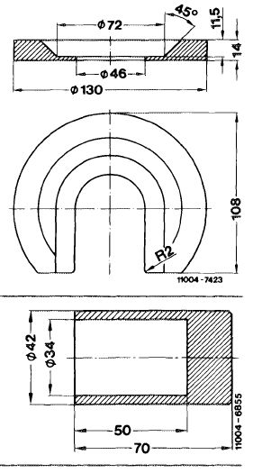
Pressing-off disk for impeller
|
 |
||
|
Pressing-in sleeve
|
|||
|
|
|||
|
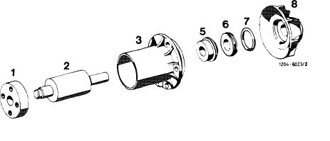
1 Fan hub 5 Slide ring seal
2 Coolant pump shaft with 6 Countering compact bearing 7 O-ring
3 Bearing housing 8 Impeller
|
 |
||
|
|
|||
|
20.8-225/1 F 2
|
|||
|
|
|||
|
|
|||
|
Disassembly
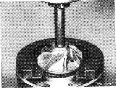
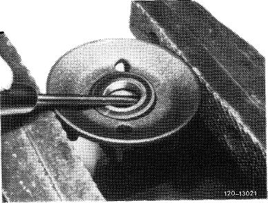
1 Press off impeller. For this purpose, place pressing-off disk between impeller and bearing housing.
|
 |
||
|
|
|||
|
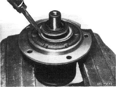
2 Apply light hammer blows at several points between bearing housing and sliding ring seal to cancel the preload and force sliding ring seal out.
|
 |
||
|
|
|||
|
3 Force counterring out of impeller.
|
 |
||
|
|
|||
|
Assembly
|
 |
||
|
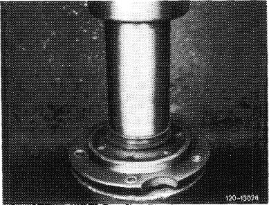
4 Slightly coat mounting bores of sliding ring seal in bearing housing with sealing compound (part No. 001 989 25 20).
Press-in or knock-in sliding ring seal by means of pressing-in sleeve.
Attention!
Support at bearing housing only and not at coolant pump shaft.
|
|||
|
|
|||
|
20.8-225/2 F 2
|
|||
|
|
|||
|
|
|||
|
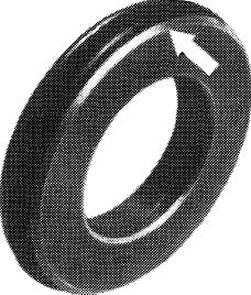
5 Coat O-ring on counterring with brake cylinder paste and push with chamfered side (arrow) into thoroughly cleaned impeller.
|
 |
||
|
|
|||
|
120 -10863
|
|||
|
|
|||
|
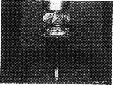
6 Clean sealing surfaces of counterring and sliding ring seal free ob dust by means of chamois cloth.
7 Degrease shaft stub of coolant pump shaft and impeller bore.
8 Press-on impeller flush with shaft while supporting coolant pump shaft.
|
 |
||
|
|
|||
|
20.8-225/3 F 2
|
|||
|
|
|||