Removal and installation of coolant pump housing
|
|
|||||
|
20—230 Removal and installation of coolant pump housing
|
|||||
|
|
|||||
|
Tightening torques
|
Nm
|
||||
|
|
|||||
|
Model 116
|
6-10
|
||||
|
|
|||||
|
Radiator drain plug
|
|||||
|
|
|||||
|
Model 123, 126
|
1.5-21)
|
||||
|
|
|||||
|
Coolant pump housing to cylinder crankcase
|
27-33
|
||||
|
|
|||||
|
Viscofan coupling to coolant pump
|
20-25
|
||||
|
|
|||||
|
l) This torque can be obtained by means of a washer or a coin.
|
|||||
|
|
|||||
|
Special tools
|
|||||
|
|
|||||
|
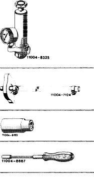
Tester for cooling system
|
 |
001 589 48 21 00
|
|||
|
Radiator cap with hose for leak test
|
605 589 00 25 00
|
||||
|
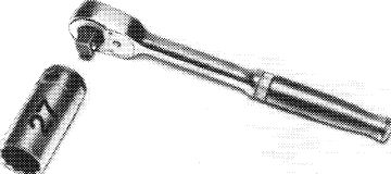
Socket 27 mm, 1/2″ square
|
001 589 65 09 00
|
||||
|
7 mm socket on flexible shaft for hose clamps with worm drive
|
123 589 12 09 00
|
||||
|
|
|||||
|
Removal
|
|||||
|
|
|||||
|
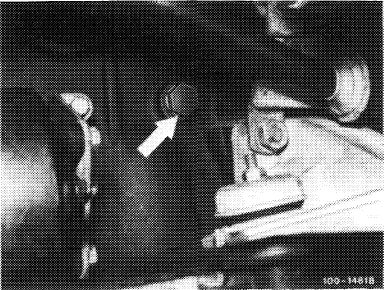
1 Completely drain coolant (20-010).
2 Remove radiator (20-420).
3 Remove fan with viscofan coupling.
4 Slacken all V-belts and remove (13-340).
5 Remove coolant pump pulley.
6 Remove crankshaft pulley and vibration damper (03-340).
|
 |
||||
|
Drain plug on cylinder crankcase
|
|||||
|
|
|||||
|
20.8-230/1 F 2
|
|||||
|
|
|||||
|
|
|||
|
7 Disconnect hot water return hose on coolant pump housing.
8 Disconnect hose between coolant thermostat housing and coolant pump housing.
9 Rotate crankshaft with tool combination until the recess in balancing disk is in front of lower fastening screw of coolant pump housing (arrow).
|
 |
||
|
|
|||
|
1100-6438,1
|
|||
|
|
|||
 |
|||
|
|
|||
|
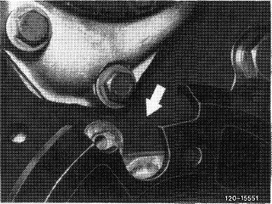
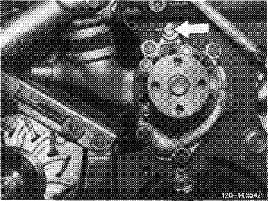
10 Unscrew vent line on coolant pump housing (arrow).
11 Unscrew coolant pump housing and remove together with coolant pump.
|
 |
||
|
|
|||
|
Installation
|
|||
|
|
|||
|
12 Install coolant pump housing with new gasket and tighten fastening screws to 27—33 Nm.
13 For further installation proceed vice versa to removal.
14 Add coolant (20-010).
15 Pressure-test cooling system with tester (approx. 1 bar gage pressure).
|
|||
|
|
|||
|
20.8-230/2 F 2
|
|||
|
|
|||
Poprzedni