Removal, installation and adjustment of front wall regulating shaft
|
|
||||
|
30—320 Removal, installation and adjustment of front wall regulating shaft
|
||||
|
|
||||
|
A. Model 116.120
|
||||
|
|
||||
|
Adjusting values in mm
|
||||
|
|
||||
|
Length of connecting rod (11) from accelerator pedal to guide lever
|
122
|
|||
|
|
||||
|
Length of pushrod (10) from longitudinal regulating shaft to accelerator pedal
|
60
|
|||
|
|
||||
|
Removal
|
 |
|||
|
1 Remove accelerator pedal (30—330).
2 Disconnect connecting rod.
3 Disconnect return spring, unscrew fastening nuts from bearing bracket and remove regulating shaft together with bearing bracket.
|
||||
|
|
||||
|
Installation
|
||||
|
|
||||
|
4 For installation proceed vice versa, while connecting return spring to inside hole. Grease bearing points as well as ball sockets of regulation with Molykote Longterm 2.
|
||||
|
|
||||
|
Adjustment
|
 |
|||
|
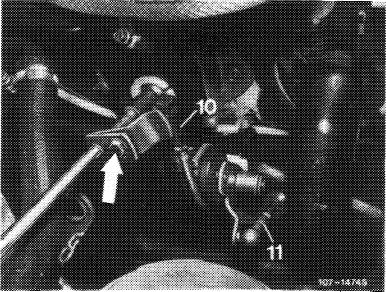
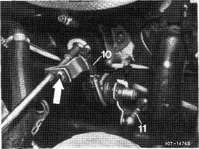
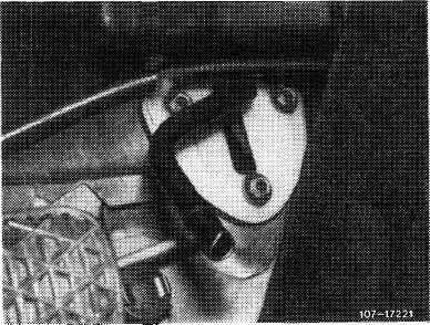
5 With engine stopped, step on accelerator pedal from inside vehicle up to stop on kickdown switch. Regulating lever on injection pump should rest against full load stop. Loosen adjusting screw (arrow), if required, adjust throttle linkage in such a manner that regulating lever rests against full throttle stop.
|
||||
|
|
||||
|
30.8-320/1 F 3
|
||||
|
|
||||
|
|
|||
|
If the full load or idle speed stop is not attained with this adjustment, set pushrod (10) from longitudinal regulating shaft to accelerator pedal to 68 mm, measured from center of ball socket to center of damping ring.
|
 |
||
|
|
|||
|
If the full load or idle speed stop is not attained with the above adjustment, set connecting rod (11) from guide lever engine compartment to accelerator pedal to 122 mm, measured from center of ball socket to center of ball socket. Adjust regulating lever inside vehicle, if required. For this purpose, loosen fastening screw (arrow), slightly release accelerator pedal and tighten fastening screw again.
|
 |
||
|
|
|||
|
30.8-320/2 F2
|
|||
|
|
|||
|
|
||
|
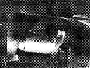
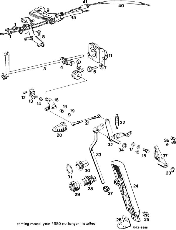
Front wall regulating shaft model 116.120
|
||
|
|
||
|
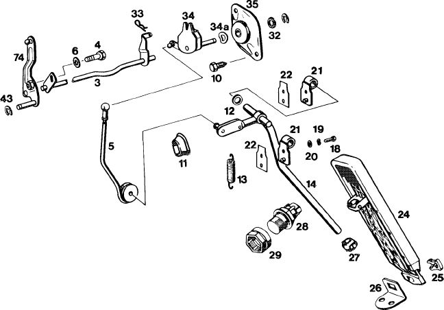
1 Plastic sleeve
3 Longitudinal regulating shaft
4 Hex. screw
5 Pull rod
6 Hex. screw
7 Corrugated washer
8 Angle lever
9 Holder
11 Holder for longitudinal regulating shaft
12 Hex. screw
13 Bearing
14 Plastic bushing
15 Hex. screw
16 Corrugated washer
17 Washer
18 Guide lever
19 Lock
20 Rubber grommet
21 Connecting rod
22 Return spring
23 Lock
24 Accelerator pedal
25 Clip
26 Fastening plate
27 Joint
28 Kickdown switch
29 Adjusting nut
30 Full throttle stop
31 Washer
32 Guide lever
33 Accelerator pedal
34 Plastic spacing ring
35 Hex. screw
36 Corrugated washer
37 Bearing
40 Bowden wire for idle speed adjuster
41 Rubber sleeve
45 Bowden wire for cruise control
 |
||
|
|
||
|
30.8-320/3 F 3
|
||
|
|
||
|
|
|||
|
B. Model 123.1
|
|||
|
|
|||
|
Length of regulating rod in mm
|
|||
|
|
|||
|
Pushrod (5 in Fig. item 5)
|
200
|
||
|
|
|||
|
Removal
|
 |
||
|
1 Remove accelerator pedal (30—330).
|
|||
|
2 Disconnect return spring and pushrod.
|
|||
|
|
|||
|
3 Unscrew plastic bearing inside vehicle and remove shaft by turning.
|
 |
||
|
Installation
|
|||
|
4 For installation proceed vice versa, while connecting return spring to inside hole.
Grease bearing points as well as ball sockets of regulation with Molykote Longterm 2.
|
|||
|
|
|||
|
Adjustment
|
 |
||
|
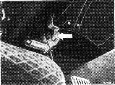
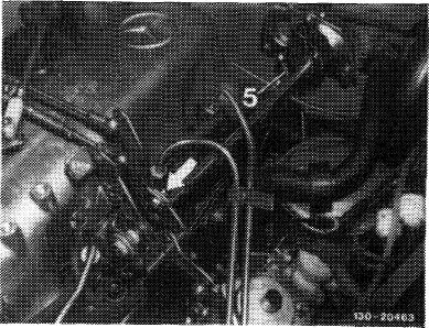
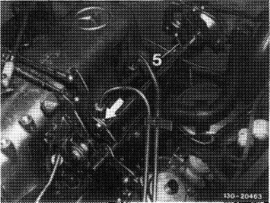
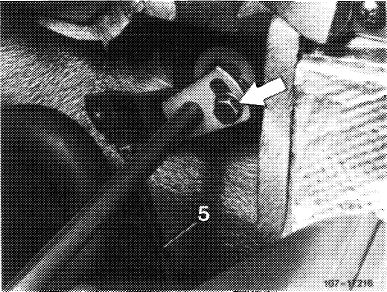
5 With engine stopped, step on accelerator pedal from inside vehicle up to stop on kickdown switch. Regulating lever on injection pump should rest against full load stop. Loosen adjusting screw (arrow), if required. Set throttle linkage in such a manner that regulating lever rests against full throttle stop.
|
|||
|
|
|||
|
30.8-320/4 F 3
|
|||
|
|
|||
|
|
|||
|
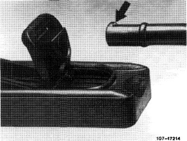
If the full load or idle speed stop is not attained with this adjustment, set pushrod (5) from longitudinal regulating shaft to accelerator pedal to 200 mm, measured from center of ball socket to center of damping ring and connect.
|
 |
||
|
|
|||
|
Front wall regulating shaft model 123.1
|
|||
|
|
|||
|
43
|
|||
|
13O3-996OC
|
|||
|
|
|||
|
30.8-320/5 F 3
|
|||
|
|
|||
|
|
||||
|
C. Model 126.120
|
||||
|
|
||||
|
Adjusting values in mm
|
||||
|
|
||||
|
Length of pushrod (5) from longitudinal regulating shaft to accelerator pedal
|
222
|
|||
|
|
||||
|
Removal
|
 |
|||
|
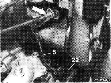
1 Disconnect return spring (22) and force-off connecting rod (5).
2 Remove accelerator pedal (30—330).
|
||||
|
|
||||
|
3 Unscrew fastening screws on bearing bracket, remove bearing bracket and accelerator pedal lever.
|
 |
|||
|
|
||||
|
Installation
|
 |
|||
|
4 For installation proceed vice versa.
Grease bearing points as well as ball sockets of regulation with Molykote Longterm 2.
The connection from accelerator pedal lever to accelerator is maintenance-free and requires no lubrication.
|
||||
|
|
||||
|
30.8-320/6 F2
|
||||
|
|
||||
|
|
|||||
|
Adjustment
5 With engine stopped, step on accelerator pedal from inside vehicle up to stop on kickdown switch. Regulating lever on injection pump should rest against full load stop. Loosen adjusting screw (arrow), if required. Adjust throttle linkage in such a manner that regulating lever rests against full load stop.
If the full throttle or idle speed stop is not attained with this adjustment, set pushrod (5) from longitudinal regulating shaft to accelerator pedal to 222 mm, measured from center of ball socket to center of damping ring.
|
 |
||||
|
|
|||||
|
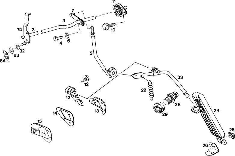
Front wall regulating shaft model 126.120
|
|||||
|
|
|||||
 |
1072-9126/1
|
||||
|
|
|||||
|
3 Longitudinal regulating shaft 22
4 Hex. screw 24
5 Pushrod 25
6 Washer 26
7 Guide lever 28
10 Hex. screw 29
11 Bearing for longitudinal 32 regulating shaft 33
12 Hex. screw 74
13 Bearing 82
14 Intermediate plate 84
15 Rubber sleeve
|
Return spring Accelerator pedal Clip
Fastening plate Kickdown switch Adjusting nut Plastic spacing ring Accelerator pedal lever Guide lever Corrugated washer Lock
|
||||
|
|
|||||
|
30.8-320/7 F 3
|
|||||
|
|
|||||