Reconditioning of coolant pump
|
|
||||
|
20—220 Reconditioning of coolant pump
|
||||
|
|
||||
|
Self-made tools
|
||||
|
|
||||
|
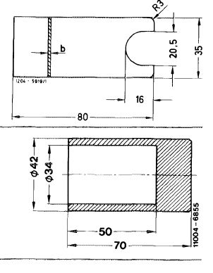
Spacing plate b = 2 mm
|
 |
|||
|
Pressing-in sleeve
|
||||
|
|
||||
|
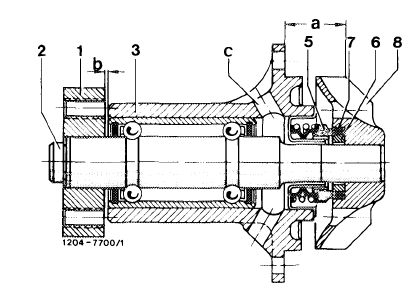
1 Fan hub
2 Coolant pump shaft with compact bearing
3 Bearing housing
5 Slide ring seal
6 Counterring
|
7 O-ring
8 Impeller
a 22.8—23.2 mm
b 2 mm
c Vent holes
|
 |
||
|
|
||||
|
Disassembly
|
 |
|||
|
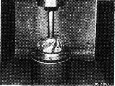
1 Support bearing housing with pertinent tubing and press out coolant pump shaft by means of a mandrel.
2 Knock sliding ring seal out of bearing housing.
|
||||
|
|
||||
|
20.8-220/1 F 2
|
||||
|
|
||||
|
|
||||
|
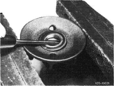
3 Remove counterring from impeller.
Note: Always replace compact bearing and fan hub following disassembly.
|
 |
|||
|
|
||||
|
Assembly
|
 |
|||
|
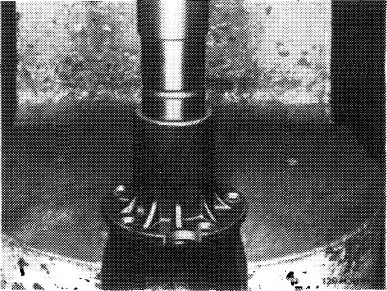
4 Press in new compact bearing flush with bearing housing by means of a tube positioned against outer race.
Do not press against coolant pump shaft.
|
||||
|
|
||||
|
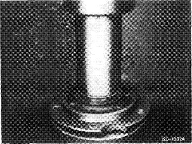
5 Coat mounting bore of sliding ring seal in bearing housing slightly with sealing compound (part No. 001 989 25 20).
Press-in or knock-in sliding ring seal with pressing-in sleeve.
Attention!
Support only against bearing housing and not against coolant pump shaft.
|
 |
|||
|
|
||||
|
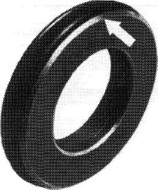
6 Coat O-ring on counterring with brake cylinder paste and push with chamfered side (arrow) into thoroughly cleaned impeller.
|
 |
120 -10863
|
||
|
|
||||
|
20.8-220/2 F 2
|
||||
|
|
||||
|
|
|||
|
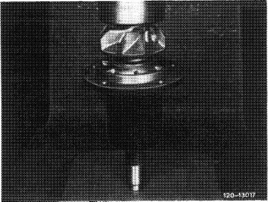
7 Clean sealing surfaces of counterring and sliding ring seal free of dust by means of a chamois cloth.
8 Degrease both shaft stubs and impeller in bore.
9 Press-on impeller flush with shaft while supporting coolant pump shaft.
|
 |
||
|
|
|||
|
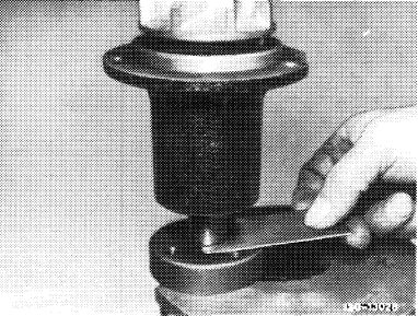
10 Heat fan hub on a hot plate to approx. 300 °C (annealing color dark — up to light blue).
Place heated fan hub on a recessed base. Hold spacing plate on coolant pump shaft, slip coolant pump shaft on fan hub and apply a blast of compressed air against hub. Wait for a few seconds until fan hub is firm and then cool immediately in water bath.
|
 |
||
|
|
|||
|
20.8-220/3 F 2
|
|||
|
|
|||
Poprzedni
Removal and installation of coolant pump
Nowsze