Coolant circuit and engine cooling
|
|
|||
|
20—005 Coolant circuit and engine cooling
|
|||
|
|
|||
|
Coolant circuit
|
|||
|
|
|||
 |
|||
|
|
|||
|
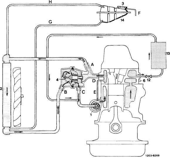
Circuit at coolant temperatures above approx. 94 °C
1 Coolant pump A
2 Radiator B
3 Closing plug, code number 100 C
4 Coolant thermostat D 6 Temperature sensor for coolant temperature readout E
12 Regulating valve for vehicle heater F
13 Heat exchanger G
14 Expansion tank H
|
To radiator
From radiator
To coolant pump (bypass line)
From cylinder head
Vent line
Overflow
Coolant line from expansion tank to radiator
Vent line to expansion tank
|
||
|
|
|||
|
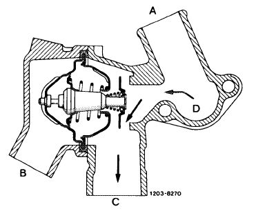
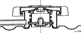
The main valve is closed up to a coolant temperature of approx. 80 °C and the bypass valve is fully opened. Flow (B) from radiator is thereby interrupted and the coolant flows via bypass line (C) directly to coolant pump.
|
 |
||
|
A To radiator
B From radiator
C Bypass line
D From cylinder head
|
|||
|
|
|||
|
20.8-005/1 F 2
|
|||
|
|
|||
|
|
|||
|
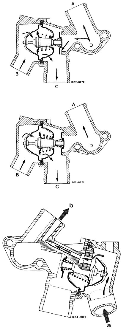
At coolant temperatures of approx. 80 C up to approx. 94 °C the main valve as well as the bypass valve are more or less open depending on engine load. The coolant flows via radiator (A) and bypass line (C) to coolant pump.
|
 |
||
|
A To radiator
B From radiator
C Bypass line
D From cylinder head
|
|||
|
At coolant temperatures above approx. 94 C the bypass line (C) is closed by the bypass valve. The entire coolant volume should flow through radiator (refer to overall diagram). It is therefore wrong to remove the coolant thermostat for better cooling of the engine.
|
|||
|
Venting of thermostat housing
|
|||
|
The thermostat housing is suspended and has an integrated, independent venting system. The air will flow to radiator and expansion tank through a bore which bypasses the coolant thermostat.
|
|||
|
a From radiator b To radiator
|
|||
|
This venting method has the following advantages:
a) When filling-in the coolant, the coolant circuit will be automatically vented.
b) Better continuous venting of coolant circuit when engine is operating.
|
|||
|
|
|||
|
20.8-005/2 F 2
|
|||
|
|
|||
|
|
|||
|
Engine cooling
|
 |
||
|
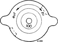
The spring-loaded closing cover (code number 100) on expansion tank establishes a gage pressure of approx. 1 bar in cooling system.
The cooling system is filled ex factory for use throughout a year with a coolant, which comprises approx. 55 % by volume of water and 45 % by volume of antifreeze.
The antifreeze provides protection down to —30 °C, and by means of additives in antifreeze prevents corrosion in cooling system. Since the additives are subject to aging, the coolant should be changed every two years.
To prevent corrosion, the concentration of the antifreeze should not drop below 30 % by volume (-20 °C antifreeze).
If no antifreeze is available and only water is filled in, be sure to add 1 % of treating compound (anti-corrosion oil 10 cc/l water).
The antifreeze increases the boiling point, which amounts to approx. 118 °C for water at 1 bar gage pressure to approx. 125 °C as a result of the mixture filled in at the factory.
The red mark of coolant thermometer begins at 122 °C.
This must be specially observed when only water and treating agent are filled in. In such a case coolant may be thrown out before the indicator of the coolant thermometer is at the red mark.
When driving under full load, on mountain roads and bumper to bumper, or following a fast ride on an express highway with subsequent traffic congestion, or when driving in areas with high outside temperatures, the coolant temperature indicator may rise up to the red mark if an antifreeze of at least —30 °C is filled in, without any ejection of coolant or faulty running of engine.
When the engine is operated for an extended period with the vehicle stopped, e.g. during a vehicle congestion, it will be of advantage to move the selector lever into position „N”. This will reduce the heat development in transmission and thereby prevent additional heating up of coolant by wax of the transmission oil cooler.
If coolant is lost by leaks in cooling system or by ejection as the result of overheating, add a pertinently prepared coolant. Losses caused by evaporation can be compensated by adding tap water.
|
|||
 |
|||
|
|
|||
|
20.8-005/3 F 2
|
|||
|
|
|||