Testing EGR
|
|
||||||||
|
14-100 Testing EGR
|
||||||||
|
|
||||||||
|
For complaints such as: Very poor engine performance, black or blue smoke.
|
||||||||
|
|
||||||||
|
Test conditions:
|
Throttle linkage correctly adjusted, connect tachometer, engine at operating temperature, run engine at idle (750 ± 100/min), steering in straightahead position, air conditioning turned off, selector lever of automatic transmission in position „P”.
Exhaust gas recirculation (EGR).
|
|||||||
|
Tested:
|
||||||||
|
|
||||||||
|
Special tools
|
||||||||
|
|
||||||||
|
Tester 0—100 mbar for vacuum and gauge pressure
|
 |
201 589 13 21 00
|
||||||
|
1DO4-12O99
|
||||||||
|
|
||||||||
|
Clamp
|
 |
000 589 40 37 00
|
||||||
|
|
||||||||
|
Test cable
|
11004-11172
|
102 589 04 63 00
|
||||||
|
|
||||||||
|
Adjusting roller
|
916 589 00 21 00
|
|||||||
|
|
||||||||
|
Conventional tools
|
||||||||
|
|
||||||||
|
Digital tester
|
e.g. Bosch, MOT 001.03 e.g. Sun, DIT9000 e.g. Sun, 1019
|
|||||||
|
|
||||||||
|
Multimeter
|
e.g. Sun, DMM—5
|
|||||||
|
|
||||||||
|
Self-made test connection
|
||||||||
|
|
||||||||
|
Distributor
|
 |
117 078 01 45
|
||||||
|
a Vacuum line 4 x 1 x 400 mm
|
||||||||
|
1074-8889
|
||||||||
|
|
||||||||
|
Test line 4 x 1 x 400 mm
|
||||||||
|
|
||||||||
|
14.8-100/1 USA F3
|
||||||||
|
|
||||||||
|
|
||||
|
A. (©)model year 1980
|
||||
|
|
||||
 |
||||
|
|
||||
|
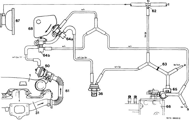
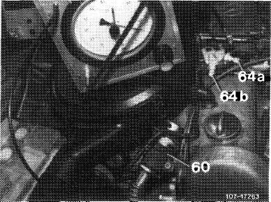
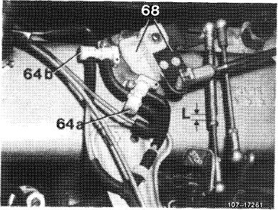
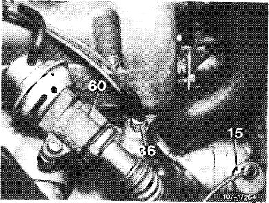
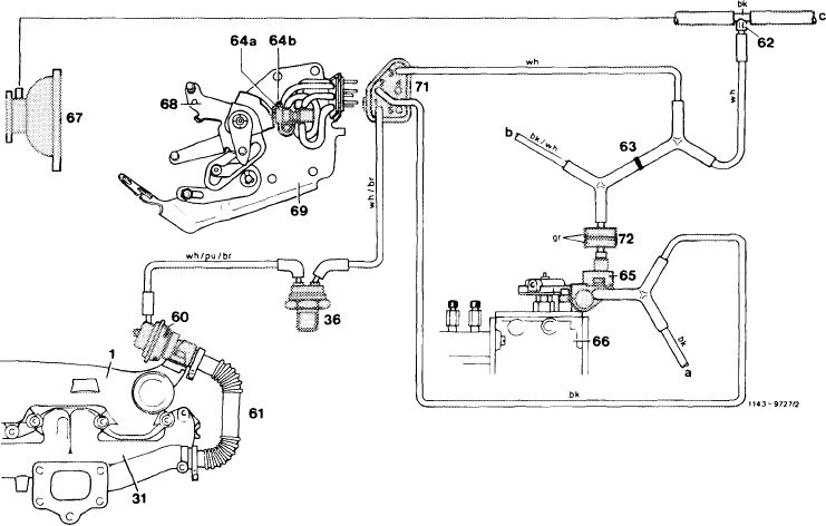
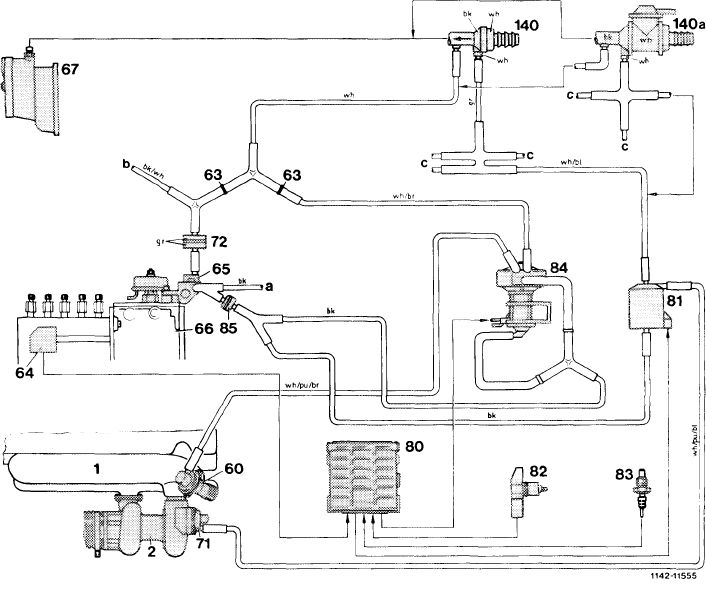
Operational diagram vacuum line layout
1 Intake manifold
31 Exhaust manifold
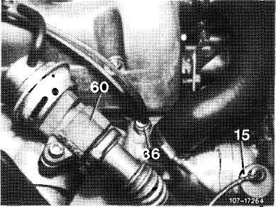
36 Thermovalve 1 7 °C/63 °F
60 Exhaust gas recirculation valve (EGR)
61 Corrugated tubing
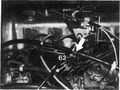
62 Orifice
63 Orifice
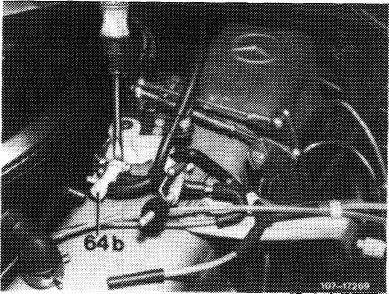
64a Switchover valve, idle speed shutoff — EGR 64bSwitchover valve, full load shutoff — EGR
|
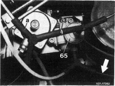
65 Vacuum control valve
66 Injection pump
67 Vacuum pump
68 Guide lever with cam
a Automatic transmission
b Vent to passenger compartment
c Brake unit
|
bk = black
br = brown
gr = green
pu = purple
re = red
wh = white
|
||
|
|
||||
|
14.8-100/2 USA 1980 F 3
|
||||
|
|
||||
|
|
|||||||||||||||||||||||||||||||||||||||
|
 |
||||||||||||||||||||||||||||||||||||||
 |
|||||||||||||||||||||||||||||||||||||||
 |
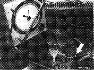
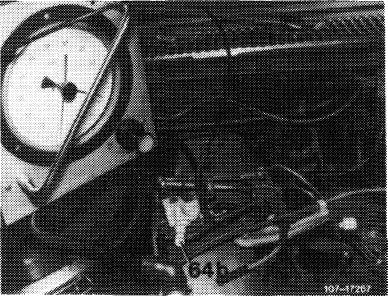
Check vacuum lines
Check all vacuum lines for control of EGR system and of automatic transmission according to operational diagram vacuum line layout for correct connection and leaks. Blow through orifice (62) at vacuum tapping point.
Check black vent line (arrow) from vacuum control valve to passenger compartment for free passage.
|
||||||||||||||||||||||||||||||||||||||
 |
|||||||||||||||||||||||||||||||||||||||
|
Check thermovalve 40 °C/104 °F (36, color code blue)
Pull off vacuum line (white/purple/ brown) on diagonal connection of thermovalve.
|
 |
||||||||||||||||||||||||||||||||||||||
|
Check vacuum line (white/brown) on distributor (a) and check for passage. If there is no passage, replace thermovalve.
|
|||||||||||||||||||||||||||||||||||||||
|
|
|||||||||||||||||||||||||||||||||||||||
|
14.8-100/3 USA 1980 F3
|
|||||||||||||||||||||||||||||||||||||||
|
|
|||||||||||||||||||||||||||||||||||||||
|
|
||||
 |
When thermovalve is cooling down, thermo-valve should have no passage at temperatures below 7 °C/45 °F.
|
|||
|
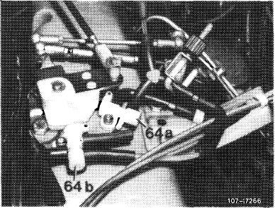
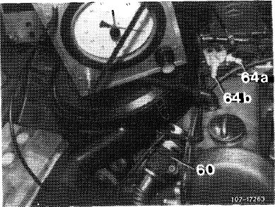
Check switchover valve (64a)
Pull connection (arrow) of vacuum line (white/purple/brown) from switchover valve.
Connect vacuum tester to free connection of switchover valve and connect with pulled off vacuum line. Vacuum readout approx. 350—500 mbar (regulating linkage at idle speed stop).
|
 |
|||
|
Leak test
Disconnect distributor of white/purple/ brown vacuum line. Vacuum should remain constant for approx. 2 minutes.
If vacuum drops, replace switchover valve.
|
||||
|
If vacuum remains constant, check switchover:
For this purpose, remove clamp, pull off connecting hose between the two switchover valves and bridge free travel on free travel rod.
Vacuum should distinctly drop. If vacuum is not dropping, replace switchover valve.
|
 |
|||
|
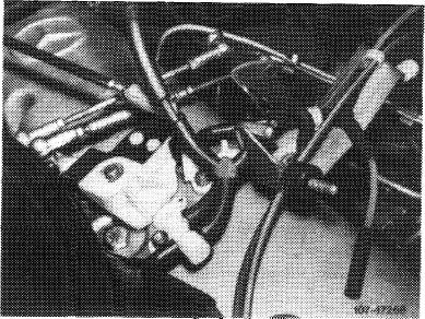
Checking switchover valve (64b)
Pull off vacuum line (white) on switchover valve (64b). Pull off vacuum line (white/purple/brown) on switchover valve (64a). Connect vacuum tester to free connection of switchover valve (64b) and connect with pulled off vacuum line (white/purple/brown). Vacuum readout 350-500 mbar.
|
 |
|||
|
|
||||
|
14.8-100/4 USA 1980 F 3
|
||||
|
|
||||
|
|
||||||
 |
Leak test
For this purpose, disconnect distributor of vacuum line (white/purple/brown). Vacuum should remain constant for approx. 2 minutes.
If vacuum drops, replace switchover valve.
If vacuum remains constant, check switchover:
For this purpose, remove clamp and pull off vacuum line (white/purple/brown) on switchover valve (64b). Switch over switchover valve with screwdriver. Vacuum should drop to „0”.
If vacuum is not dropping to „0”, replace switchover valve.
|
 |
||||
 |
||||||
 |
||||||
|
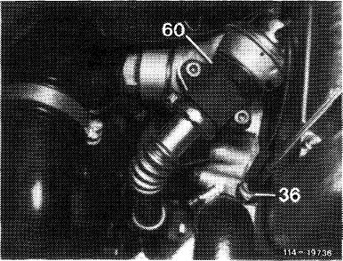
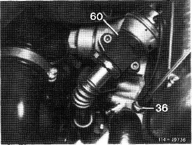
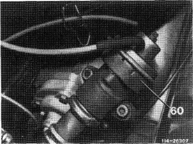
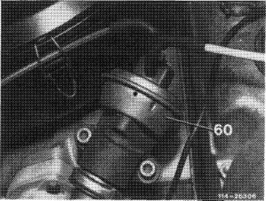
Checking EGR valve (60)
Switch over switchover valve (64a) by bridging free travel „L” on free travel rod. Pull off vacuum line on EGR valve and plug on again.
|
||||||
|
EGR valve should audibly close.
|
EGR valve not closing.
|
|||||
 |
Replace EGR valve (60).
|
 |
||||
 |
||||||
 |
||||||
|
|
||||||
|
14.8-100/5 USA 1980 F 3
|
||||||
|
|
||||||
|
|
|||||
|
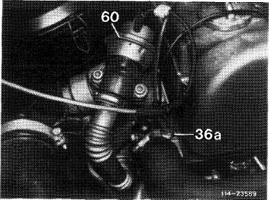
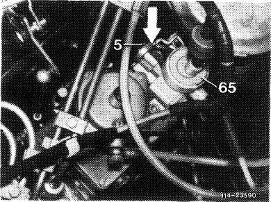
Checking vacuum control
Connect vacuum tester to vacuum line between EGR valve (60) and switchover valve (64b). Increase idle speed to 1000 ± 10/min by operating regulating linkage (do not pull on stop lever)
|
 |
||||
|
Vacuum amounts to 320-350 mbar.
|
Vacuum is below or above specified value.
|
||||
 |
 |
||||
 |
|||||
|
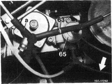
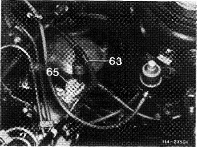
Check orifice (63)
Check if orifice is open and blow through, if required.
|
|||||
|
Change orifice (63)
If the vacuum is not attained or is exceeded, install the next larger size orifice, if the vacuum is too high and the next smaller orifice if the vacuum is too low.
If the correct vacuum is not attained by the installation of another orifice, replace vacuum control valve (65).
|
|||||
|
|
|||||
|
End of test
|
|||||
|
|
|||||
|
14.8-100/6 USA 1980 F 3
|
|||||
|
|
|||||
|
|
||||||||||||||||||||||||||||||||||||
|
B. <@> starting model year 1981
|
||||||||||||||||||||||||||||||||||||
|
|
||||||||||||||||||||||||||||||||||||
 |
||||||||||||||||||||||||||||||||||||
|
|
||||||||||||||||||||||||||||||||||||
|
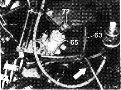
Operational diagram, vacuum line layout
1 Intake manifold
31 Exhaust manifold
36 Thermovalve 40 °C/104°F
60 Exhaust gas recirculation valve (EGR)
61 Corrugated tubing
62 Orifice
63 Orifice
64a Switchover valve, idle speed shutoff — EGR 64bSwitchover valve, full throttle shutoff — EGR 65 Vacuum control valve
|
66 Injection pump
67 Vacuum pump
68 Guide lever with cam
69 Valve plate
71 Central plug
72 Vacuum damper
a Vent to passenger compartment
b Automatic transmission
c Brake unit
|
|
||||||||||||||||||||||||||||||||||
|
|
||||||||||||||||||||||||||||||||||||
|
Checkup
|
||||||||||||||||||||||||||||||||||||
|
|
||||||||||||||||||||||||||||||||||||
|
Note: At begin of test, yellow orifice (63) should be installed.
|
||||||||||||||||||||||||||||||||||||
|
|
||||||||||||||||||||||||||||||||||||
|
14.8-100/7 USA starting 1981 F3
|
||||||||||||||||||||||||||||||||||||
|
|
||||||||||||||||||||||||||||||||||||
|
|
|||||
|
Testing EGR
Connect vacuum tester between EGR valve (60) and straight connection of thermovalve (36). At idle, with throttle linkage at idle stop, no vacuum should be indicated. Advance control linkage until free travel of free travel rod is eliminated (do not pull on stop lever). The vacuum should now amount to 350-500 mbar.
|
 |
||||
|
Idle, no vacuum present.
Vacuum of 350— 500 mbar is attained.
|
Vacuum present. Vacuum not attained or exceeded.
|
||||
 |
|||||
 |
 |
||||
|
Check vacuum lines
Check all vacuum lines for control of EGR and automatic transmission according to operating diagram vacuum line layout for correct connection and leaks. Blow through orifice (62) in vacuum tapping point, if required.
Check black vent line (arrow) from vacuum control valve to passenger compartment for free passage.
|
|||||
 |
|||||
|
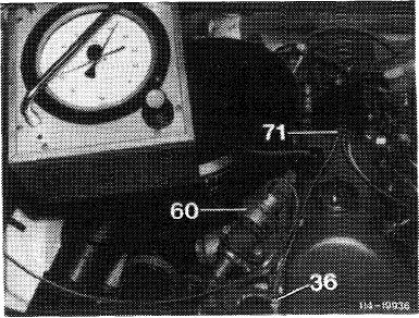
Check thermovalve 40 °C/104 °F (36, color code blue)
Pull off white/brown vacuum line on diagonal connection of thermovalve.
Pull off white/purple/brown vacuum line on EGR valve and blow through.
If there is no passage, remove thermovalve.
|
 |
||||
|
|
|||||
|
14.8-100/8 USA starting 1981 F3
|
|||||
|
|
|||||
|
|
||||
 |
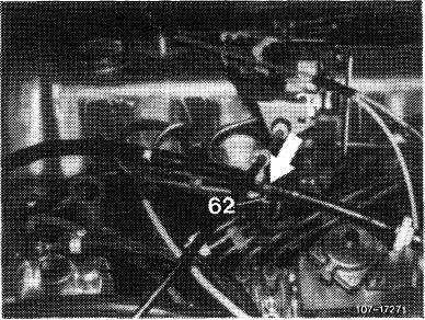
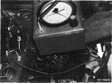
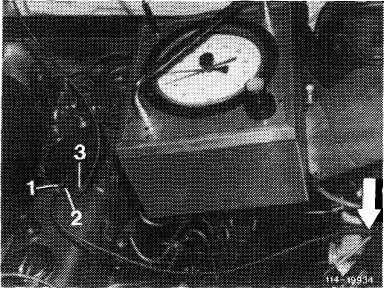
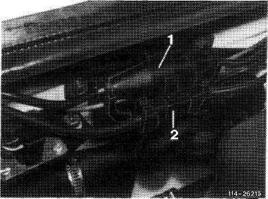
Check switchover valve (64a)
Pull central plug (71) from valve plate (69). Connect test line between tapping point (black orifice, arrow) on vacuum line for brake unit and valve plate connection (1). Connect vacuum tester to connection (3). Close connection (2).
Vacuum readout at switchover:
Idle speed (throttle linkage at idle speed
stop) „0” mbar.
Bridge idle speed (do not pull on stop
lever) approx. 700-800 mbar.
Leak test:
Let throttle linkage return to idle speed
stop, stop engine.
Vacuum should remain constant for
approx. 2 minutes.
Pull closing cap from connection (2).
Bridge idle speed.
Vacuum should drop to „0”.
If test values are not attained: Replace switchover valve (64a).
|
 |
||
 |
||||
|
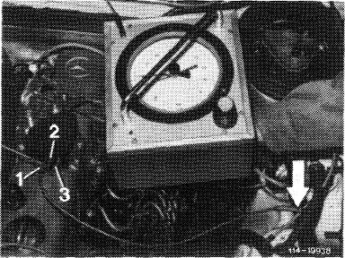
Check switchover valve (64b)
Pull central plug (71) from valve plate (69). Connect test line between tapping point (black orifice, arrow) on vacuum line brake unit and valve plate connection (1). Connect vacuum tester to connection (2).
Close connection (3), start engine.
Vacuum readout:
Idle speed (regulating linkage on idle
speed stop) approx. 700—800 mbar.
Leak test:
Disconnect tapping point for test line (arrow). Stop engine, vacuum should remain constant for approx. 2 minutes.
|
 |
|||
|
|
||||
|
14.8-100/9 USA starting 1981 F3
|
||||
|
|
||||
|
|
|||||
 |
Vacuum readout at switchover: Throttle linkage at full throttle stop, vacuum should remain constant. Let throttle linkage return to idle speed stop and pull off test line.
Vacuum should drop to „0”.
If test values are not attained, renew switchover valve (64b).
|
 |
|||
 |
|||||
 |
|||||
|
Checking EGR valve (60)
Start engine. Operate switchover valve (64a) by eliminating free travel „L” on free travel rod. Pull off vacuum line on EGR valve and plug-on again.
|
|||||
|
EGR valve should audibly close.
|
EGR valve not closing.
|
||||
 |
 |
||||
|
Replace EGR valve (60).
|
|||||
 |
|||||
|
|
|||||
|
14.8-100/10 USA starting 1981 F3
|
|||||
|
|
|||||
|
|
|||
|
Note: Check adjustment of vacuum control valve prior to test.
|
 |
||
 |
|||
 |
|||
 |
|||
|
|
|||
|
14.8-100/11 USA starting 1981 F3
|
|||
|
|
|||
|
|
|||||
|
C.
|
model year 1984 California
|
||||
|
|
|||||
 |
|||||
|
|
|||||
|
Function diagram vacuum line installation
1 Intake manifold
2 Exhaust gas turbocharger 50 EGR-valve
63 Orifice 0.5 mm
64 Control rod travel indicator
65 Vacuum control valve
66 Injection pump
67 Vacuum pump
71 Circulating air safety valve
72 Vacuum damper 80 Control unit
|
81 Switchover valve
82 Rpm sensor
83 Temperature sensor coolant (NTC)
84 Pressure converter
85 Vent filter
140 Check valve, model 123
140a Check valve, model 126
a Vent line to passenger compartment
b To automatic transmission
c Remaining consumers
|
bk = black bl = blue br = brown gr = green pu = purple re = red wh = white
|
|||
|
|
|||||
|
14.8-100/12 USA 1984 California F 3
|
|||||
|
|
|||||
|
|
||||
 |
||||
|
|
||||
|
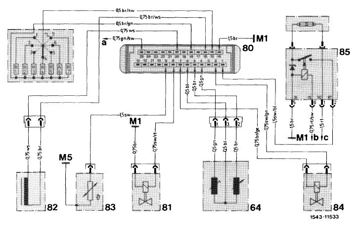
Electric wiring diagram
64 Control rod travel indicator
80 Control unit
81 Switchover valve
82 Rpm sensor
83 Temperature sensor
84 Pressure converter
85 Overvoltage protection
86 Compensating plug
|
M1 Main ground behind instrument cluster
M5 Ground, engine
a To revolution counter
b To fuse capsule, terminal 15
c To supporting lug, terminal 30
|
bl = blue br = brown ge = yellow gn = green it = red sw = black
|
||
|
|
||||
|
14.8-100/13 USA 1984 California F 3
|
||||
|
|
||||
|
|
||||||
|
Short test
|
 |
|||||
|
Test EGR-valve (60) with engine stopped
Activate EGR-valve with approx. 300 mbar vacuum. Pull off vacuum line.
|
||||||
|
EGR-valve closes audibly
|
not closing
|
 |
||||
 |
Renew EGR-valve.
|
|||||
 |
||||||
|
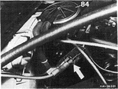
Testing voltage at pressure converter (84)
Engine stopped, ignition switched on. Pull plug from pressure converter and connect with multimeter (arrow), push button „V=” and read nominal value 12 V.
|
||||||
|
Readout in order
|
not in order
|
 |
||||
 |
|
|||||
|
Test overvoltage protection and electric activation according to wiring diagram.
|
||||||
 |
||||||
|
|
||||||
|
14.8-100/14 USA 1984 California F3
|
||||||
|
|
||||||
|
|
|||||
|
Testing vacuum control
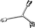
Connect vacuum tester with Y-distributor to EGR-valve (60).
Read vacuum values at the following engine speeds:
|
 |
||||
|
1/min
|
mbar
|
||||
|
700-2600
from approx. 2400
3000
|
280-360 slowly dropping
approx. 60
|
||||
|
|
|||||
|
Vacuum values in order
|
not in order
|
||||
|
|
|||||
 |
 |
||||
|
Perform testing individual components.
|
|||||
|
|
|||||
|
End of test
|
|||||
|
|
|||||
|
14.8-100/15 USA 1984 California F3
|
|||||
|
|
|||||
|
|
||||||
|
Testing individual components
|
||||||
|
</Testing EGRtd> |
||||||
|
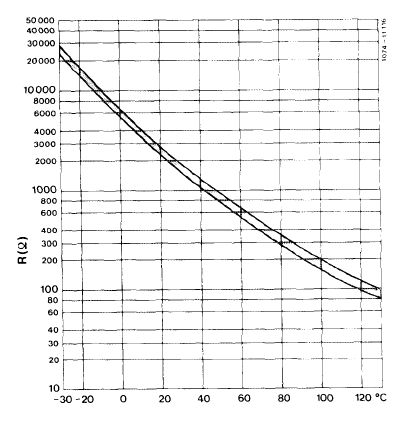
Testing temperature sensor for coolant (83)
Engine stopped.
Pull plug from temperature sensor for coolant.
Test resistance against ground.
|
 |
|||||
|
For nominal value refer to diagram.
Test resistance at three temperature measuring
points.
|
||||||
 |
||||||
|
Example:
+ 20 °C = 2.2-2.8 + 80 °C = 290-364 +100°C= 140-222
|
||||||
|
Test
values in order
|
not in order
|
|||||
 |
 |
|||||
|
Renew temperature sensor
|
||||||
|
End of test
|
||||||
|
|
||||||
|
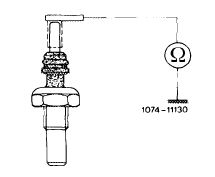
Testing rpm sensor (82)
Engine stopped.
Separate clutch (2) and test resistance with
multimeter.
Readout: 1.9 ±0.2
|
 |
|||||
|
in order
|
not in order
|
 |
||||
 |
Renew rpm sensor.
|
|||||
 |
||||||
|
|
||||||
|
14.8-100/16 USA 1984 California F 3
|
||||||
|
|
||||||
|
|
||||||
|
Connection as above.
Push „V” button.
Read test value at the following engine speed:
|
 |
|||||
|
1/min
|
V
|
|||||
|
700-800
|
>4M
|
|||||
|
Test values in order
|
not in order
|
 |
||||
 |
|
|||||
|
Renew rpm sensor.
|
||||||
|
|
||||||
|
End of test
|
||||||
|
|
||||||
|
Voltage increasing with increasing engine speed.
|
||||||
|
|
||||||
|
Testing control rod travel indicator
Engine stopped, separate clutch (1). With multimeter in position £2 (measuring range up toap-prox. 100 fi) and test resistance according to drawing.
Readout: 1-2 = approx. 25 ± 2 2-3 = approx. 25 ± 2 1-3 = approx. 50 ± 6
|
 |
|||||
|
Readout in order
|
not in order
|
|||||
|
|
||||||
 |
 |
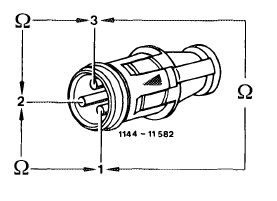 |
||||
|
Exchange injection pump with control and travel indicator.
Attention!
The control rod travel is set by manufacturer on test bench. Do not remove or change its function.
|
||||||
|
End of test
|
||||||
|
|
||||||
|
14.8-100/17 USA 1984 California F 3
|
||||||
|
|
||||||
|
|
|||||||
|
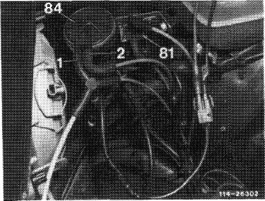
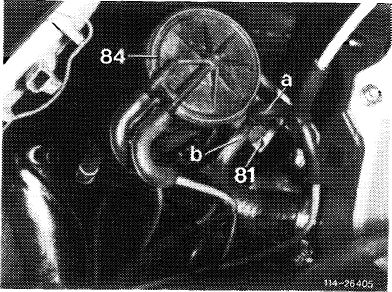
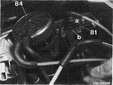
Testing pressure converter (84)
Connect vacuum tester to vacuum line of connection (2). Run engine at idle speed. Read vacuum value. Nominal value approx. 450 mbar.
|
 |
||||||
|
Vacuum in order
|
not in order
|
||||||
 |
 |
||||||
|
Test vacuum lines according to function diagram. Test vacuum pump (43—660).
|
|||||||
 |
 |
||||||
|
Connect vacuum tester with Y-distributor to connection (1). Connect multimeter with test cable to pressure converter. Push button ,,mA”
Read test values at the following engine speeds:
|
|||||||
|
1/min
|
mbar
|
mA
|
|||||
|
700-2600 from approx. 2400 approx. 3000
|
280-360 dropping slowly approx. 60
|
^ 530
£370 0
|
|||||
|
|
|||||||
|
Test
values in order
|
not in order
|
||||||
 |
|||||||
 |
|
||||||
|
Current values in order, renew pressure converter.
Current values not in order, perform activation test according to electric wiring diagram. Renew control unit, if required.
|
|||||||
|
|
|||||||
|
End of test
|
|||||||
|
|
|||||||
|
14.8-100/18 USA 1984 California F3
|
|||||||
|
|
|||||||
|
|
||||||||
|
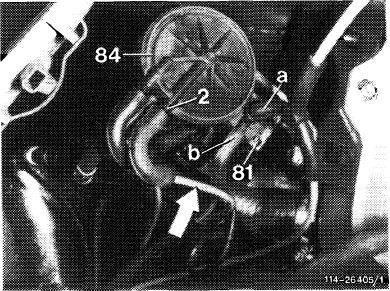
Testing switchover valve (81)
Connect vacuum tester with Y-distributor to connection (a). Run engine at idle speed. Read vacuum value. Nominal value > approx. 600 mbar.
|
 |
|||||||
|
Vacuum in order
|
not in order
|
 |
||||||
 |
|
|||||||
|
Test vacuum lines according to vacuum diagram. Test vacuum pump (43—660).
|
||||||||
|
|
 |
 |
||||||
|
Connect vacuum tester with Y-distributor to connection (b). Connect multimeter with switchover valve. Push button „V=”. Read test values at the following engine speeds:
|
||||||||
|
1/min
|
mbar
|
Volt
|
||||||
|
700-800
1000-2500
>3000
|
approx. 600 0
|
0
approx. 12 0
|
||||||
|
Test
values in order
|
||||||||
|
not in order
|
||||||||
|
|
||||||||
 |
 |
|||||||
|
Voltage data in order, renew switchover valve.
Voltage data not in order, perform activation test according to electric wiring diagram. Renew control unit, if required.
|
||||||||
|
|
||||||||
|
End of test
|
||||||||
|
|
||||||||
|
14.8-100/19 USA 1984 California F3
|
||||||||
|
|
||||||||